Eureka AIR delivers breakthrough ideas for toughest innovation challenges, trusted by R&D personnel around the world.

Applicator brush

a brush and application technology, applied in the field of brushes, can solve the problems of affecting the applicator effect of brushes, affecting the smooth blending depending, undesirable streaking, and affecting the application effect of brushes,

Active Publication Date: 2011-03-01
FM BRUSH
View PDF6 Cites 38 Cited by
  • Summary
  • Abstract
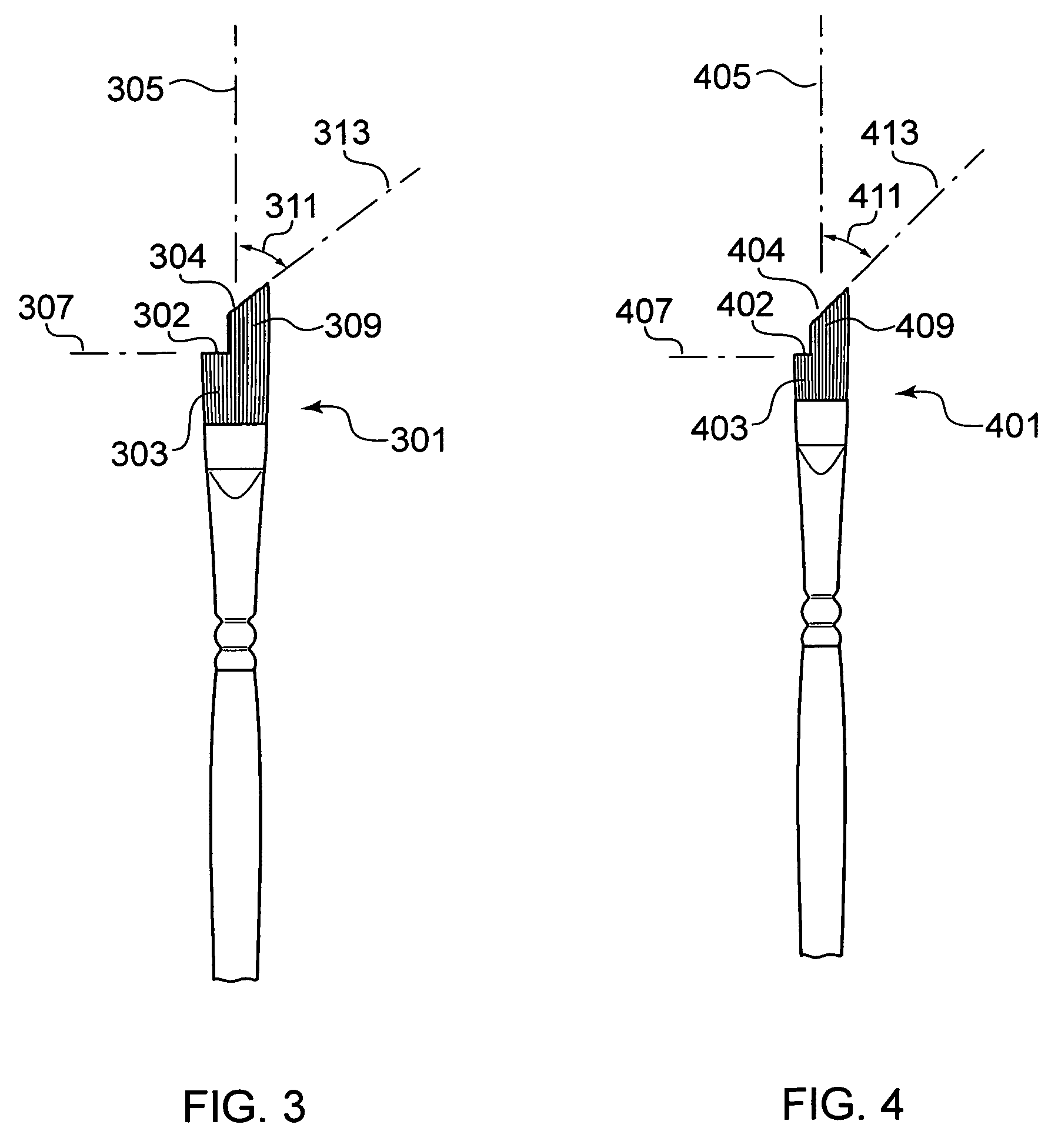
  • Description
  • Claims
  • Application Information

AI Technical Summary

Benefits of technology

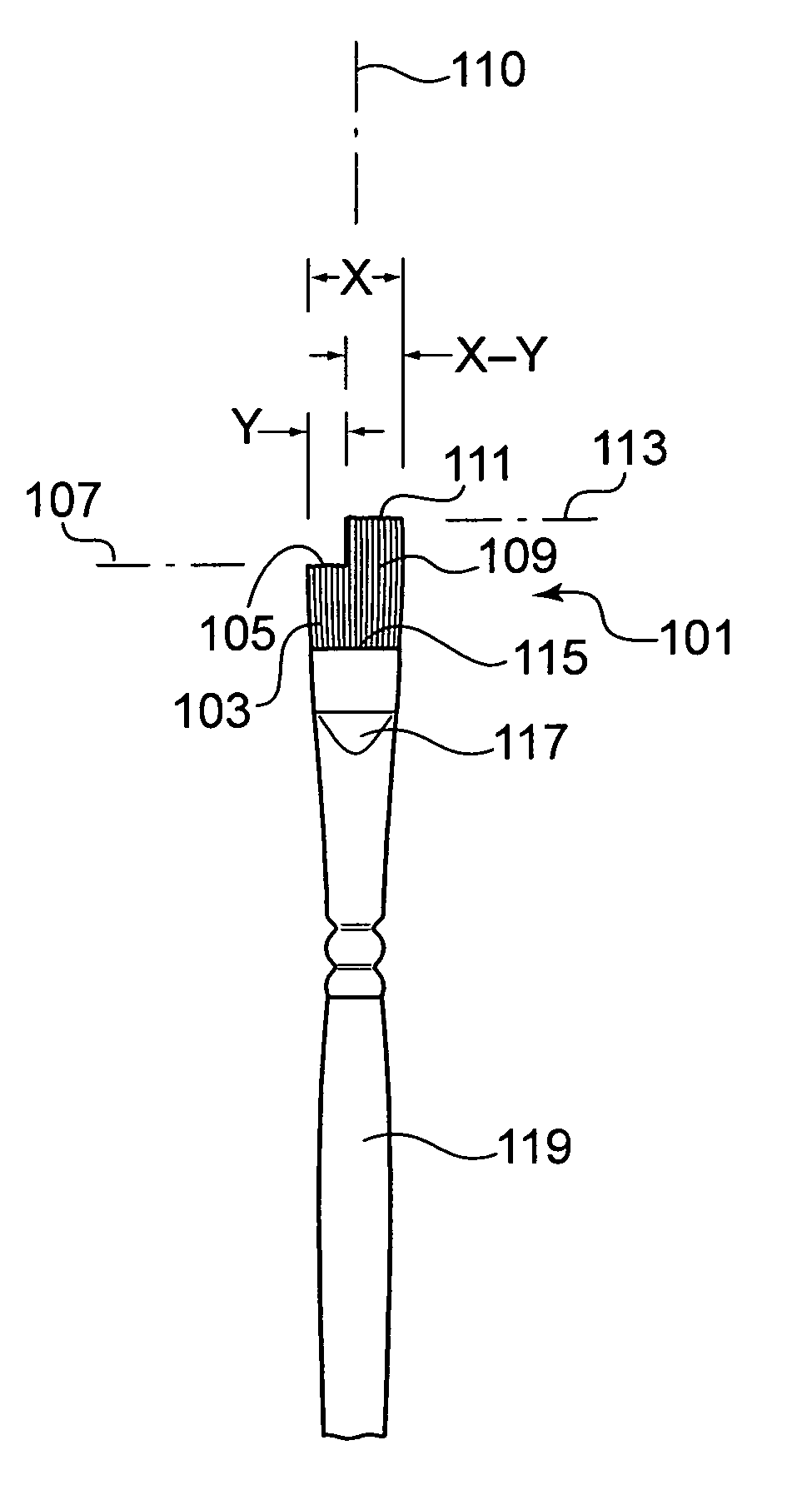
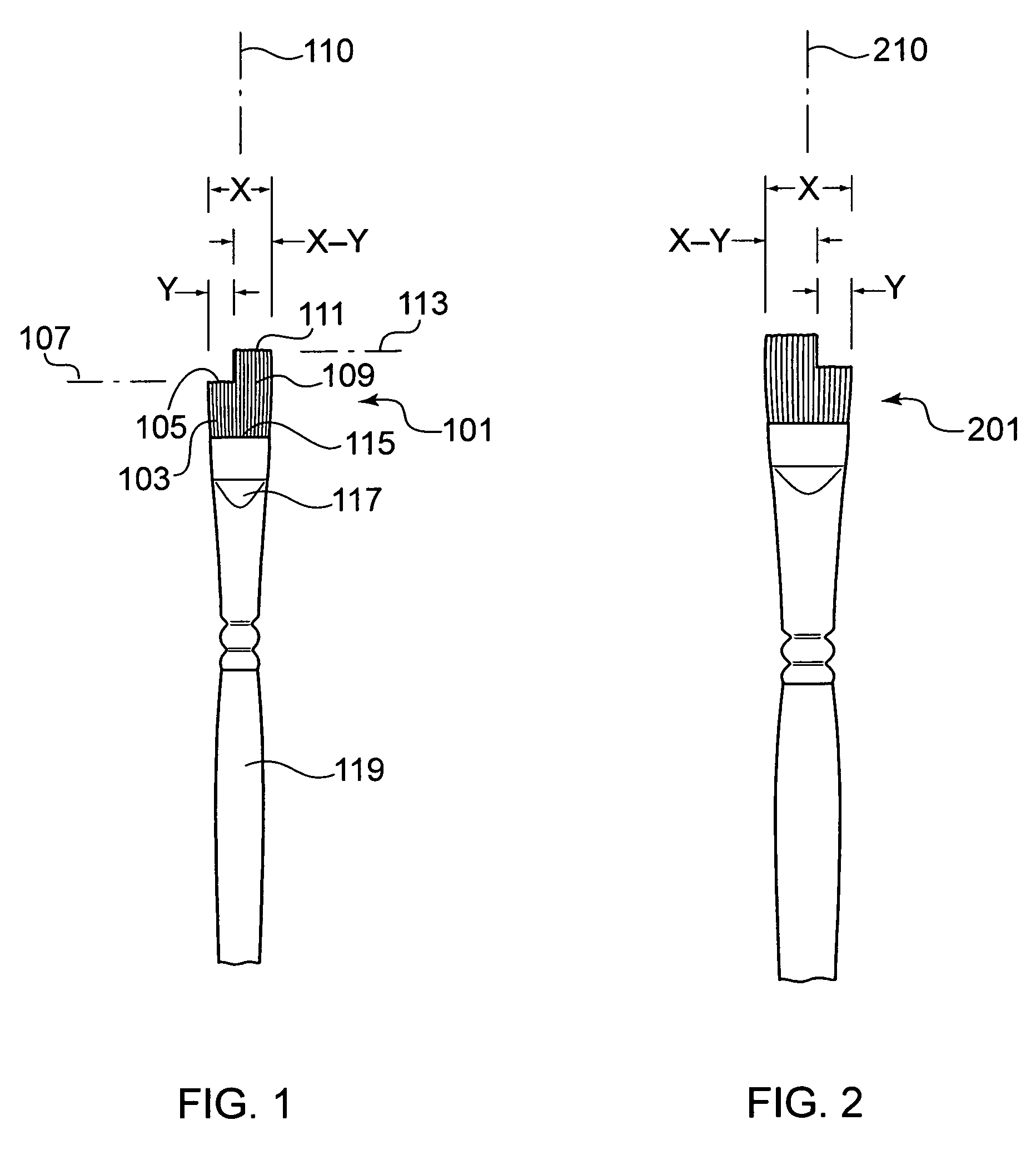
[0007]The present invention provides an applicator brush instrument having a specialized bristle head comprised of a tuft of bristles arranged in a substantially laterally flattened formation having a width X and secured at a proximal end to a ferrule or bushing. The bristle head comprises at least two sets of bristles, each configured in a separate and distinct arrangement from each other on a single bristle head, advantageously enabling, e.g., separate take-up of different substances (pigments, dyes, powders, etc.) whether in solid, liquid or semi-solid form, and simultaneous and controlled application of the multiple substances in, e.g., a single stroke. During use, the brush head according to one aspect of the present principles can maintain physical separation of multiple substances, yet allows their simultaneous distribution, application and / or blending if desired.
[0008]The bristles of the multiple sets are provided comprised of particular lengths, proportions and edge configurations. Accordingly, the creation of unique and complex patterns, textures and effects during application of various substances using a variety of techniques is facilitated. A brush according to the present invention may be utilized with advantageous effect in a variety of applications, such as cosmetic applications, art and crafts, painting, etc., and may be used to apply a variety of substances, preferably flowable, in solid, liquid or semi-solid form.

Problems solved by technology

However, such brushes are generally limited in their applicator effects, especially, e.g., with respect to the application of multiple product types.
Even a slight pause in time however, can negatively affect smooth blending depending, e.g., on the nature (volatility, consistency, etc.) of the materials used.
Undesirable streaking, or defined striping / spotting can occur if there is any delay in the time between deposition of materials on a surface and blending of same.

Method used


Image

  • Applicator brush
  • Applicator brush
  • Applicator brush

Examples


Embodiment Construction

[0021]Referring now to the Figures, FIGS. 1-6 depict front views of brush heads according to various exemplary embodiments of the present invention. FIGS. 7, 8 and 9 depict right side, left side and top views, respectively, of the brush head of FIG. 1. A brush head according to one aspect of the present invention is comprised of or ‘split’ into at least two ‘sets’ of bristles having at least two distinct edges, both sets being generally flattened in shape when secured to a ferrule. In one embodiment, the bristle sets are comprised of different lengths and may include edges situated on various planes / angles / degrees of curvature. Such configurations advantageously enable separate and / or simultaneous contact of either / both bristle set edges onto a surface during use. Improved control, precision and blending is thus enabled, as well as application of multiple materials, whether of solid, semi-solid or liquid form, either separately or concurrently.

[0022]A brush head according to an aspe...


PUM


Abstract

An applicator brush for applying a material to a surface is provided having a brush head of a width X arranged along a central axis. The brush head includes a first set of bristles having proximal base ends attached to a ferrule and distal ends defining a first edge situated in a substantially straight first plane perpendicular to the central axis. The first set of bristles have a first width Y, wherein Y<X. A second set of bristles is provided having proximal ends attached to the ferrule and distal ends defining a second edge situated in a second plane having a second width (X-Y). A length of each bristle in the first and second sets is defined as a distance between its proximal attachment point and its distal end.

Description

TECHNICAL FIELD OF THE INVENTION[0001]The present invention generally relates to brushes and, more particularly, to applicator brushes for improved application of materials for, e.g., cosmetic and artistic purposes.BACKGROUND OF THE INVENTION[0002]Brushes made with natural and / or synthetic bristles are used for a variety of activities involving the application of various products and substances. Specially designed brushes may be employed where specific control is needed during application of e.g., cosmetic substances and artistic materials used in creating works of art.[0003]There are numerous cosmetic and artistic substances and materials provided in an array of forms designed for application to various surfaces, such as the skin, as well as a variety of permeable and non-permeable surfaces such as paper, canvas, wood, ceramics, plastics, etc. Regardless of the form of a cosmetic / art material, e.g., whether in liquid, semi-liquid or solid forms, a primary object involves achieving ...

Claims


Application Information

Patent Timeline
Patent Type & Authority Patents(United States)
IPC IPC(8): A46B15/00
CPCA46B9/021A46B9/028A46B2200/1046A46B2200/205
Inventor MINK, JEFFREY
Owner FM BRUSH
Why Eureka
Eureka Blog
Learn More