
Liquid crystal display device

a technology of liquid crystal display and light guide plate, which is applied in the direction of semiconductor devices, optical light guides, instruments, etc., can solve the problems of reducing the light emission efficiency restricting positioning, and increasing the operation temperature of so as to improve the reliability of the backlight, stabilize the positional relationship, and facilitate the alignment between the light emitting diodes and the light guide plate.

Inactive Publication Date: 2009-12-24
PANASONIC LIQUID CRYSTAL DISPLAY CO LTD
View PDF4 Cites 14 Cited by
  • Summary
  • Abstract
  • Description
  • Claims
  • Application Information

AI Technical Summary

Benefits of technology

[0010]In the liquid crystal display device having the backlight using light emitting diodes, when the number of light emitting diodes to be used is increased for higher luminance, the operation temperature of the light emitting diodes increases, resulting in a problem that the light emitting efficiency of the light emitting diodes is reduced. Therefore, the heretofore known backlight using light emitting diodes employs a configuration which can effectively dissipate the heat generated by the light emitting diodes.
[0012]An object of the invention is to provide a technology capable of effectively dissipating heat of light emitting elements and making alignment between light emitting diodes and a light guide plate easy in a liquid crystal display device having a light guide plate type backlight.
[0025]According to the invention, in a liquid crystal display device having a light guide plate type backlight which uses light emitting diodes, the heat of the light emitting diodes can be effectively dissipated. Further, according to the invention, the alignment between the light emitting diodes and a light guide plate is easy, and the positional relationship can be stabilized. Accordingly, the liquid crystal display device of the invention can improve the reliability of a backlight.

Problems solved by technology

In the liquid crystal display device having the backlight using light emitting diodes, when the number of light emitting diodes to be used is increased for higher luminance, the operation temperature of the light emitting diodes increases, resulting in a problem that the light emitting efficiency of the light emitting diodes is reduced.
However, such a configuration causes another problem that the heat dissipating member restricts the positioning of the light emitting diodes.
Therefore, problems relating to the reliability of the backlight arise in that, for example, the positional relationship between the light emitting diodes and the light guide plate varies for each liquid crystal display device, and that luminance fluctuates each device.

Method used


Image

  • Liquid crystal display device
  • Liquid crystal display device
  • Liquid crystal display device

Examples


Embodiment Construction

[0046]Hereinafter, the invention will be described in detail together with an embodiment with reference to the drawings. Throughout the drawings for explaining the embodiment, elements having the same function are denoted by the same reference numerals, and the repetitive description thereof is omitted.

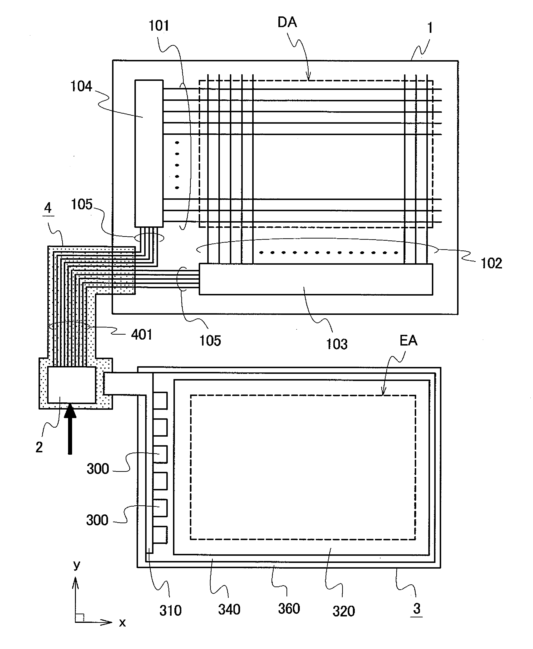
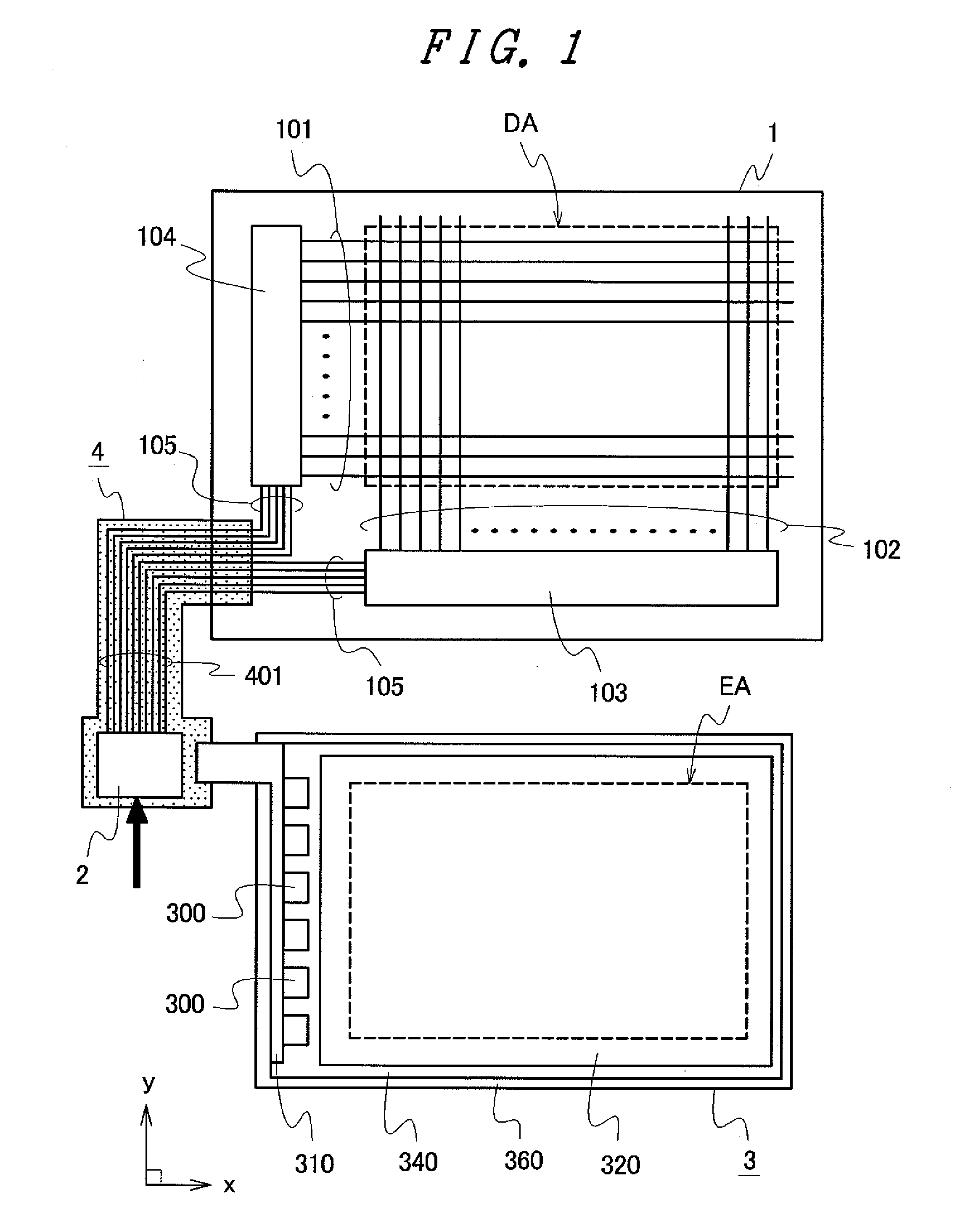
[0047]FIG. 1 is a schematic view showing an example of a schematic configuration of a liquid crystal display device of an embodiment according to the invention.

[0048]The invention is applied to, for example, a liquid crystal display device having a light guide plate type backlight. The liquid crystal display device includes, for example, a liquid crystal display panel 1, a control circuit 2, and a backlight as a planar lighting device. The control circuit 2 is formed on a flexible wiring board 4 where wirings 401 or the like are disposed on the surface of a film-like insulating substrate (not shown), for example.

[0049]The liquid crystal display panel 1 is a display panel having a liqu...


PUM


Abstract

A liquid crystal display device includes a liquid crystal display panel and a backlight irradiating the liquid crystal display panel with light. The backlight has a plurality of light emitting elements, a circuit board on which the light emitting elements are mounted, a light guide plate irradiating the liquid crystal display panel with the light emitted from the light emitting elements, a resin mold housing the light guide plate, and a metal case housing the resin mold. The resin mold has a plurality of protruding portions on a bottom surface facing the metal case. The metal case has a plurality of opening portions on a bottom surface facing the resin mold. The protruding portions of the resin mold and the opening portions of the metal case are fitted together.

Description

CROSS-REFERENCE TO RELATED APPLICATION[0001]The present application claims priority from Japanese application JP 2008-162181 filed on Jun. 20, 2008, the content of which is hereby incorporated by reference into this application.BACKGROUND OF THE INVENTION[0002]1. Field of the Invention[0003]The present invention relates to a liquid crystal display device and particularly to a technology effectively applied to a liquid crystal display device having a light guide plate type backlight which uses light emitting diodes (LEDs) as light sources.[0004]2. Background Art[0005]Heretofore, liquid crystal display devices have been used for, for example, a display part of a portable electronic device because it is thin, light in weight, and consumes less power.[0006]However, since the liquid crystal display device is not self-luminous, it requires a lighting means for clearly displaying a video or image. For the lighting means of the liquid crystal display device, a planar lighting device general...

Claims


Application Information

Patent Timeline
Patent Type & Authority Applications(United States)
IPC IPC(8): G02F1/1333
CPCG02B6/0088H01L2224/48091H01L2224/49107H01L2924/00014
Inventor WATANABE, SABURO
Owner PANASONIC LIQUID CRYSTAL DISPLAY CO LTD
Learn More