
Method for power sharing and controlling the status of a display wall

Active Publication Date: 2009-12-17
BARCO NV +1
View PDF21 Cites 25 Cited by
  • Summary
  • Abstract
  • Description
  • Claims
  • Application Information

AI Technical Summary

Benefits of technology

[0007]An object of the present invention is to provide additional operational security when there is a power failure of a power unit in display wall, in particular of a LED display wall.
[0023]It is an alternative or additional object of the invention to provide a method which allows for easy topographical identification of broken components of a display wall.
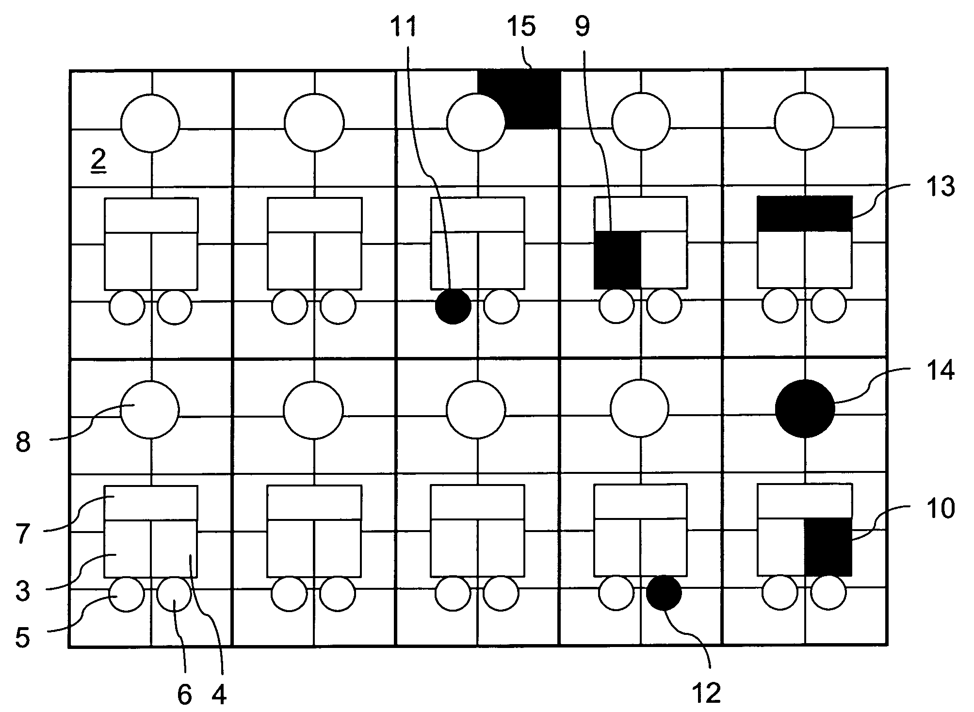
[0028]Further, and according to another preferred embodiment of the invention, the picture and the display wall are separated in at least one, preferably multiple tiles, wherein the status and / or diagnostic information of each tile of the display wall is shown in its respective position in the picture. This means, that the build-up of the display wall that is made up by multiple tiles, is represented within the picture in its topological correct position, whereby the picture can be made up by tiles as well. This kind of separation of the picture allows for an easy location of faulty tiles of the display wall being displayed in the picture at the correct position.
[0029]It is further preferred that a tile comprises multiple modules and wherein status and / or diagnostic information of each module of the display wall is shown in its respective position in the picture. Given that the status and / or diagnostic information of the module is displayed in its respective and topographically correct position within the picture, it becomes simple for a technician to locate the correct module that must be replaced due to a failure or malfunction.
[0033]Generally, the picture may show only devices visible from the front of the display wall. According to a preferred embodiment of the invention, the picture shows devices, which are not visible from the front side of the display wall. This way, an onsite support engineer may easily locate the position of faulty device, which is not visible from the front side of the display wall.
[0035]According to a further embodiment of the invention, during a failure of a power supply the outputs of other power supplies are linked together such that the tile and / or module of the respective failed power supply continues to display the picture. This means that for the respective tile and / or module status and / or diagnostic information is still visible even when the respective power supply is not working anymore due to the failure. This means also that due to the redistribution of power along some tiles and / or modules, the maximum brightness of the display may decrease by about (N−1) / N of the maximum brightness, whereby N represents the number of power supplies linked together. In a further embodiment of the invention redundant power supplies may be used to avoid power supply failures.

Problems solved by technology

The disadvantage of this topology is if one power supply unit fails, all the LED modules powered by this unit will go to black, therefore a ‘black hole’ will be generated.
In prior art arrangements it is difficult to locate damaged modules and / or devices.
Especially on big display walls it is difficult and time-consuming to determine the exact location of a broken module or device within the display wall.

Method used


Image

  • Method for power sharing and controlling the status of a display wall
  • Method for power sharing and controlling the status of a display wall
  • Method for power sharing and controlling the status of a display wall

Examples


Embodiment Construction

[0042]The present invention will be described with respect to particular embodiments and with reference to certain drawings but the invention is not limited thereto but only by the claims. The drawings described are only schematic and are non-limiting. In the drawings, the size of some of the elements may be exaggerated and not drawn on scale for illustrative purposes. Where the term “comprising” is used in the present description and claims, it does not exclude other elements or steps. Where an indefinite or definite article is used when referring to a singular noun e.g. “a” or “an”, “the”, this includes a plural of that noun unless something else is specifically stated.

[0043]The term “comprising”, used in the claims, should not be interpreted as being restricted to the means listed thereafter; it does not exclude other elements or steps. Thus, the scope of the expression “a device comprising means A and B” should not be limited to devices consisting only of components A and B. It ...


PUM


Abstract

Described is a method for power sharing of a display wall, in particular of a LED display wall having a plurality of display modules, and a plurality of N power supply units, each for driving a number of display modules, whereby during a failure of a first power supply unit of the plurality of N power supply units, the outputs of other power supply units are linked together such that the module or modules driven by the first and failed power supply continue(s) to operate, by redistribution of power from the other power supply units. Power sharing is also described in the context of a method for controlling the status of a display wall, in particular of a LED display wall, controlled by a central unit. The method includes collecting status and / or diagnostic information of the display wall inputted to the central unit; converting the status and / or diagnostic information to a picture; and displaying the picture on the display wall.

Description

FIELD OF THE INVENTION[0001]The invention relates to the field of power sharing and / or controlling the status of a display wall, in particular of a LED display wall, which is controlled by a central unit.TECHNICAL BACKGROUND[0002]Display walls are used in different application areas, such as indoor and outdoor advertising, for events such as concerts, sport games or general entertainment. Display walls are available in different sizes up to ten or more square meters. Different content, such as video, text or graphics can be shown on display walls, both as static or moving information.[0003]Display walls are often made up of light emitting devices (LED) whereby these LED walls are often made up of multiple tiles and modules. Each tile may break up into 64 discrete modules, whereby each module may break up into 8 by 11 pixels that are represented each by one LED. These modules can be connected to a central unit inside the tile structure, by means of cables, each providing power and si...

Claims


Application Information

Patent Timeline
IPC IPC(8): G05F1/00
CPCG06F3/1446G09F9/33G09G2330/12G09G2330/02G09G2330/08G09G3/32
Inventor LI, ZHENG MINLI, BEN LIANGXIAO, LERYCKAERT, PAULJIANG, CHANG BIN
Owner BARCO NV
Learn More