
Method and apparatus for measuring catheter contact force during a medical procedure

Active Publication Date: 2009-12-17
ADVANCED CARDIAC THERAPEUTICS
View PDF8 Cites 101 Cited by
  • Summary
  • Abstract
  • Description
  • Claims
  • Application Information

AI Technical Summary

Benefits of technology

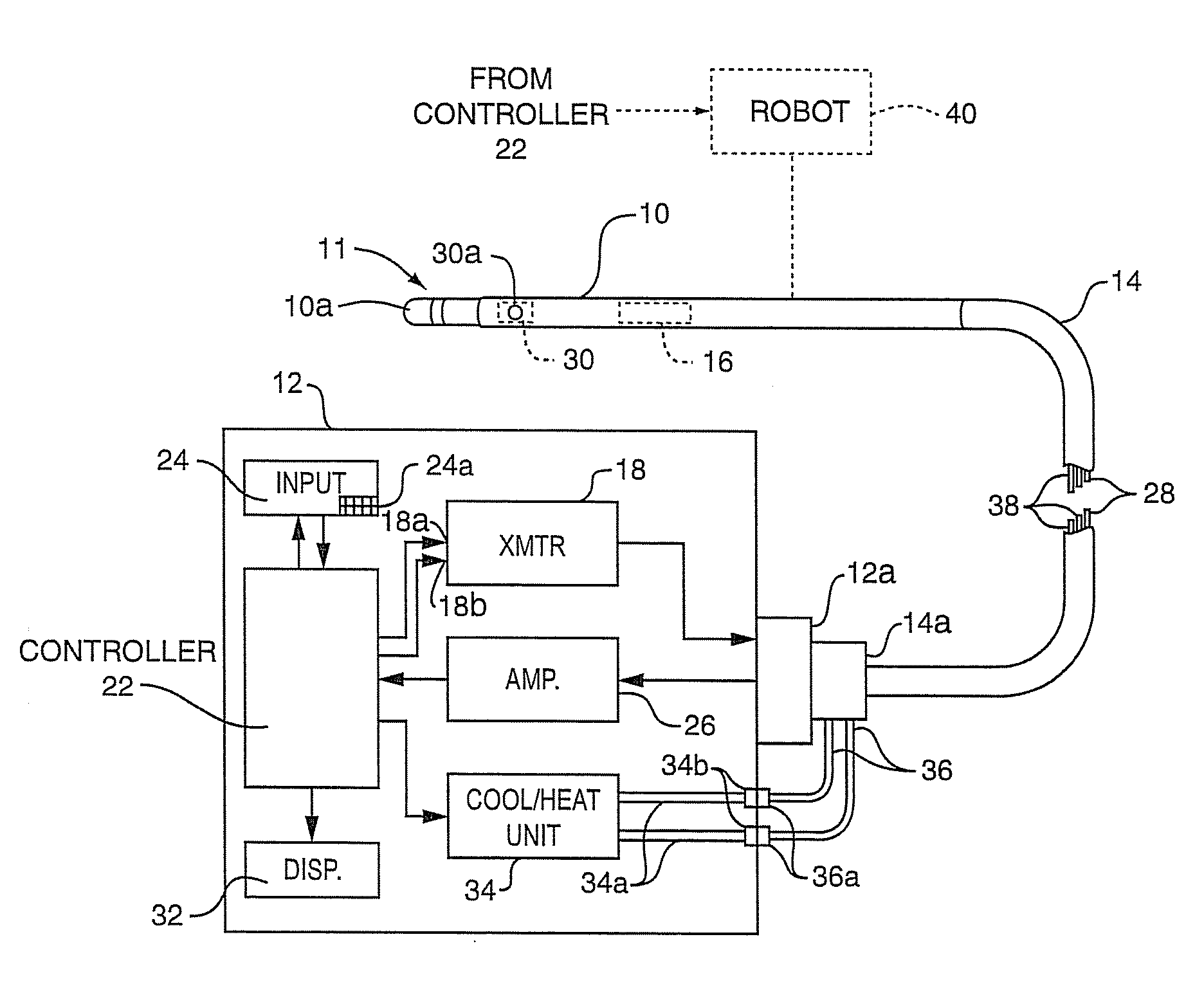
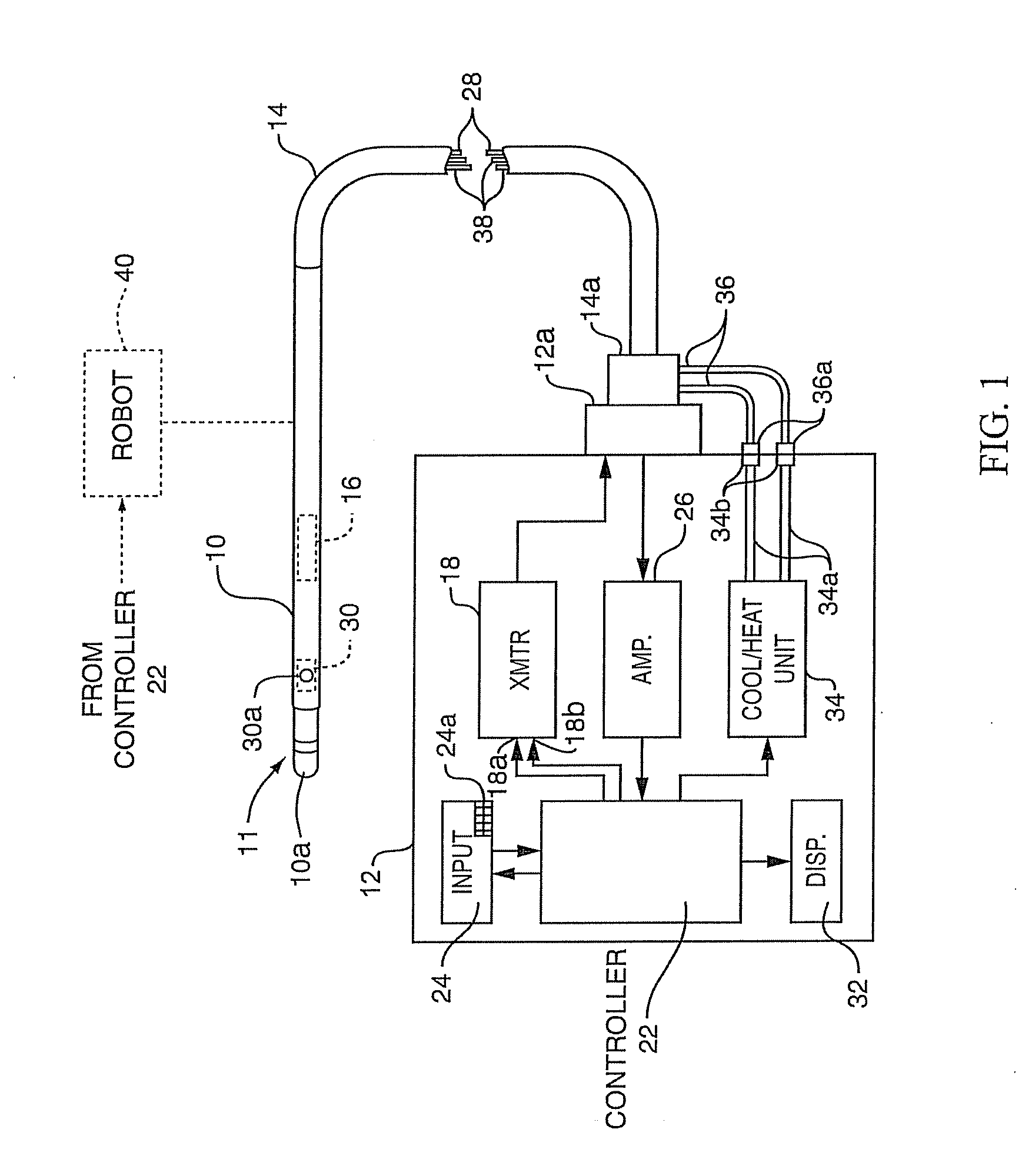
[0014]Accordingly, this invention aims to provide a method for accurately measuring catheter contact force during placement of a catheter or probe inside a human or animal body.
[0015]A further object of the invention is to provide such a method which minimizes the chances of causing tissue damage or catheter damage during placement of a catheter in a body.
[0016]Another object of this invention is to provide a method for accurately measuring catheter contact force during cardiac ablation.

Problems solved by technology

The point of highest resistance in this circuit, normally at the interface between the probe tip and the heart tissue, is the region which heats the most and thus may cause irreversible damage to the heart tissue.
A signal from the sensor is applied to a display in the external unit, enabling the operating surgeon to adjust the power as needed to provide sufficient heating of the tissue to cause necrosis, but not enough to result in surface charring of the tissue that could cause a stroke and / or the formation of bubbles (popping) that could rupture the heart vessel wall.
The problem is that the surgeon may not be able to appreciate how much contact force he / she is actually applying to the tissue.
Indeed, there have been reported cases where the operating physician or robot places too much force on the tissue, cauing the probe tip to perforate the heart wall.
This condition, known as cardiac perforation, can lead to serious complications including death of the patient.
However, with this artificial cooling came the undesired consequence that the attending surgeon no longer has the temperature feedback described above because the temperature sensor in the probe no longer takes accurate tissue temperature readings at the point of contact.
Another disadvantage of the prior apparatus of this type is the operating surgeon has to work within the radiation field of the antenna catheter during the entire ablation procedure.
Such exposure over the years could cause irreparable harm to the surgeon.
However, until now it has proven difficult to control a robotic arm with sufficient accuracy to enable placement of an antenna catheter against the heart tissue with just the right amount of contact force to enable tissue ablation at the point of contact without damaging the heart as described above.
One can envision other medical procedures, e.g. angioplasty, colonoscopy, etc., wherein the movements of a catheter in the body could cause an excessive contact force to be applied to the opposing portions of the tissue and probe resulting in damage to one or both of same.

Method used


Image

  • Method and apparatus for measuring catheter contact force during a medical procedure
  • Method and apparatus for measuring catheter contact force during a medical procedure
  • Method and apparatus for measuring catheter contact force during a medical procedure

Examples


working example 1

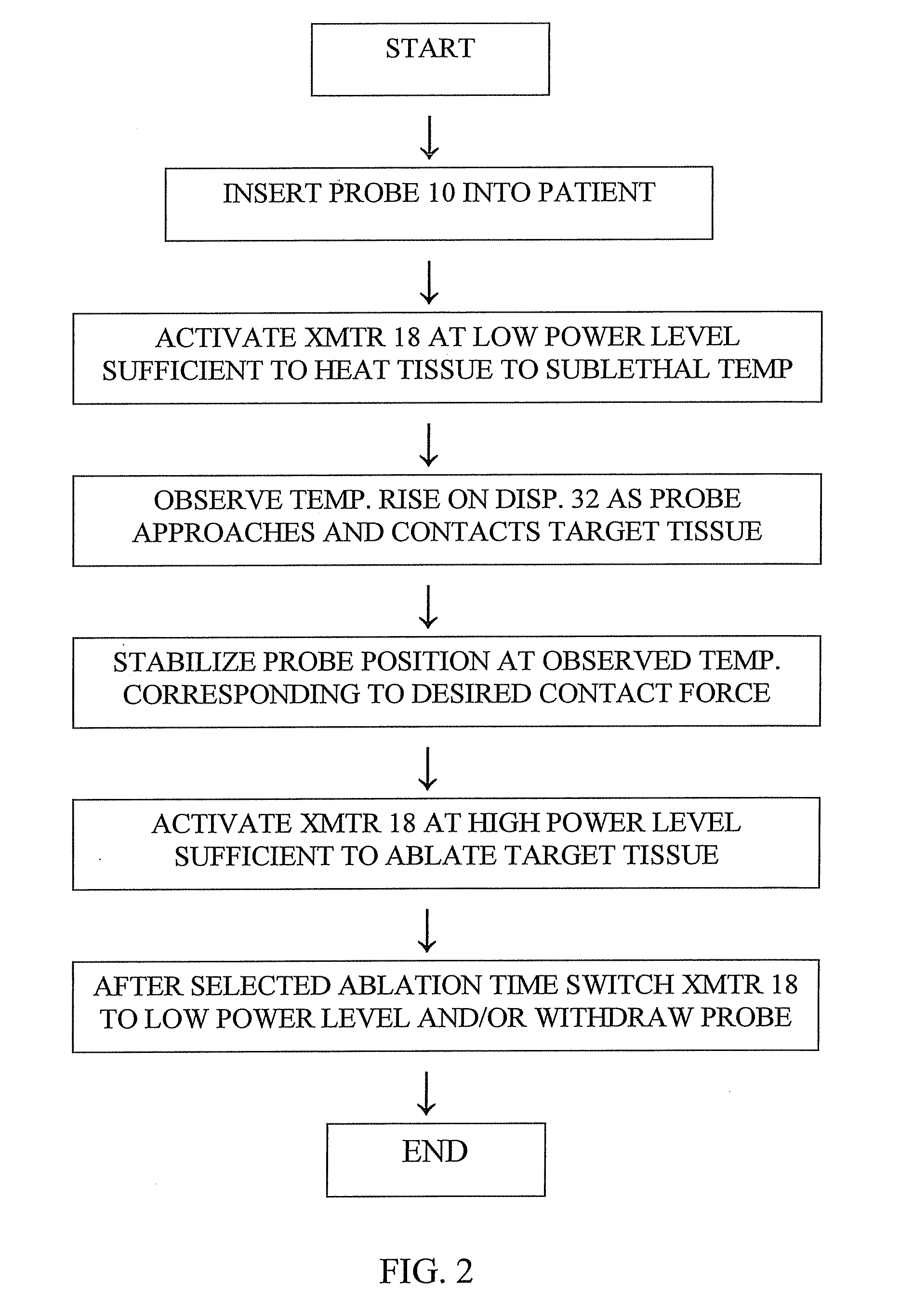
[0052]A test was performed to determine if there is a power level which keeps the temperature rise in tissue below 5° C. at full contact but causes enough of a temperature rise in the radiometer output signal or reading to accurately determine the contact force applied to the tissue.

[0053]Testing was performed with the delivery of low power, i.e. 0, 1, 2 and 4 watts, to the antenna in the catheter and the catheter was attached to a force sensor. The catheter tip was positioned 2-3 mm above the target tissue and then moved slowly until it reached the tissue and then moved into the tissue.

[0054]FIG. 3 graphs a typical “2 watt” run using our method, recording the force exerted by the probe on the tissue and the radiometer reading while 2 watts of power were applied. As shown in FIG. 3, the radiometer reading indicated the beginning of a temperature rise as the probe touched the tissue at time 50 seconds and the temperature rise clearly tracked the increase in force exerted on the tissu...

working example 2

[0056]A second test was performed to determine if there is a high power level but short time which keeps the temperature rise in tissue below 5° C. at full contact, but causes enough of a temperature rise in the radiometer to accurately determine the contact force applied to the tissue.

[0057]Testing was performed with the delivery of high power, i.e. 30 watts, for a short period of time, i.e. 10 and 5 seconds, to the antenna in the catheter and the catheter was attached to a force sensor. The catheter tip was positioned 2-3 mm above the target tissue and then moved slowly until it reached the tissue and then moved into the tissue. The antenna was stopped when the load on the tissue was 5 grams and then high power was pulsed on for 10 seconds. This was repeated for every 5 gram increment until 50 grams, which is thought to correspond to the maximum allowable force which should be exerted on the heart tissue.

[0058]FIG. 5 shows an example of the temperature rise in the radiometer durin...


PUM


Abstract

A method for measuring the contact force exerted on tissue by a probe for heating the tissue and containing an antenna which is connected to a radiometer whose output reading indicates the temperature at depth of the tissue contacted by the probe comprises displaying the output reading of the radiometer, applying sufficient power to the probe to heat the tissue to a selected first temperature that is not lethal to the tissue, moving the probe into contact with the tissue, observing the increase in the displayed temperature reading that occurs when the probe contacts the tissue, and advancing the probe toward the tissue until the displayed temperature reading reaches a value corresponding to a selected tissue contact force. After the probe position in the tissue has stabilized, the applied power to the probe may be increased to heat the tissue to a selected second temperature that is lethal to tissue for a sufficient time to ablate the tissue followed by lowering the tissue heating to a sub-lethal temperature. Apparatus for practicing the method is also disclosed.

Description

RELATED APPLICATION[0001]This application claims the benefit of Provisional Application No. 61 / 061,305, filed Jun. 13, 2008.BACKGROUND OF THE INVENTION[0002]This invention relates to a medical antenna catheter apparatus and a method for measuring the contact force applied by an antenna catheter to tissue during a medical procedure.[0003]Our technique may be used any time it is desireable to avoid placing too much force on a medical catheter or the tissue contacted thereby, such as when steering a catheter along a passage in the body or when stabilizing the catheter at a particular location in the body. It is especially advantageous for use during a cardiac ablation procedure. Accordingly, the invention will be described in that context.[0004]Antenna catheters or probes utilize electromagnetic radiation to simultaneously controllably heat, and detect the temperature of, tissue contacted by a catheter or probe. By placing the probe at the region of interest in the body, in this case a...

Claims


Application Information

Patent Timeline
IPC IPC(8): A61B18/18
CPCA61B18/10A61B18/1492A61B18/18A61B19/46A61B2019/465A61B2017/00243A61B2018/00023A61B2018/00642A61B2018/00791A61B2017/00084A61B90/06A61B2090/065
Inventor LENIHAN, TIMOTHY J.ALLISON, ROBERT C.CARR, KENNETH L.VAN DER SLUIS, PETER
Owner ADVANCED CARDIAC THERAPEUTICS
Learn More