
Method and system for controlling the climate in a house

a technology for controlling the climate and the house, applied in the direction of instruments, heating types, static/dynamic balance measurement, etc., can solve the problems of different costs associated with the different heat sources, the inability to compensate for the different costs of floor heating, and the inability to influence the indoor climate and the cost of use. , to achieve the effect of enhancing the ability of responding, reducing the time constant, and increasing the thermal convection

Inactive Publication Date: 2009-12-10
DANFOSS AS
View PDF55 Cites 8 Cited by
  • Summary
  • Abstract
  • Description
  • Claims
  • Application Information

AI Technical Summary

Benefits of technology

The present invention provides a method for improving the indoor climate by controlling various sources of thermal energy in a way that takes into account the importance of compliance with a comfort criterion and the cost of energy. The method allows for a balance between the two to be achieved, providing better comfort and more efficient use of energy. The method can be applied to a variety of sources of thermal energy, such as radiators, floor heating systems, and heated electrically. The method also takes into account various physical quantities that can influence the climate, such as temperature, humidity, and light intensity, and adjusts the amount of energy released accordingly. Overall, the invention provides a more effective and economical way to control the indoor climate.

Problems solved by technology

These heat sources are characterised by their dissimilarity in influencing the indoor climate and the costs of use.
A floor heating system, on the other hand, contributes very little to the removal of cold draught, and the time constant or inertia of the floor heating system renders floor heating completely unsuitable for compensation of a sudden climatic fluctuation.
In addition to the differences in the influence of the climate, different costs may be associated with the different heat sources.
As an example, it is in many countries more expensive to use an electrical heater than a water based heating system (e.g. with an oil-fired boiler).

Method used


Image

  • Method and system for controlling the climate in a house
  • Method and system for controlling the climate in a house
  • Method and system for controlling the climate in a house

Examples


Embodiment Construction

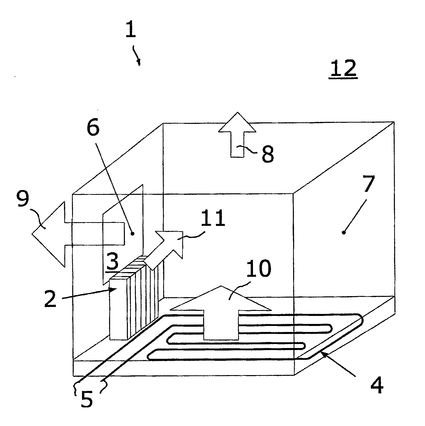
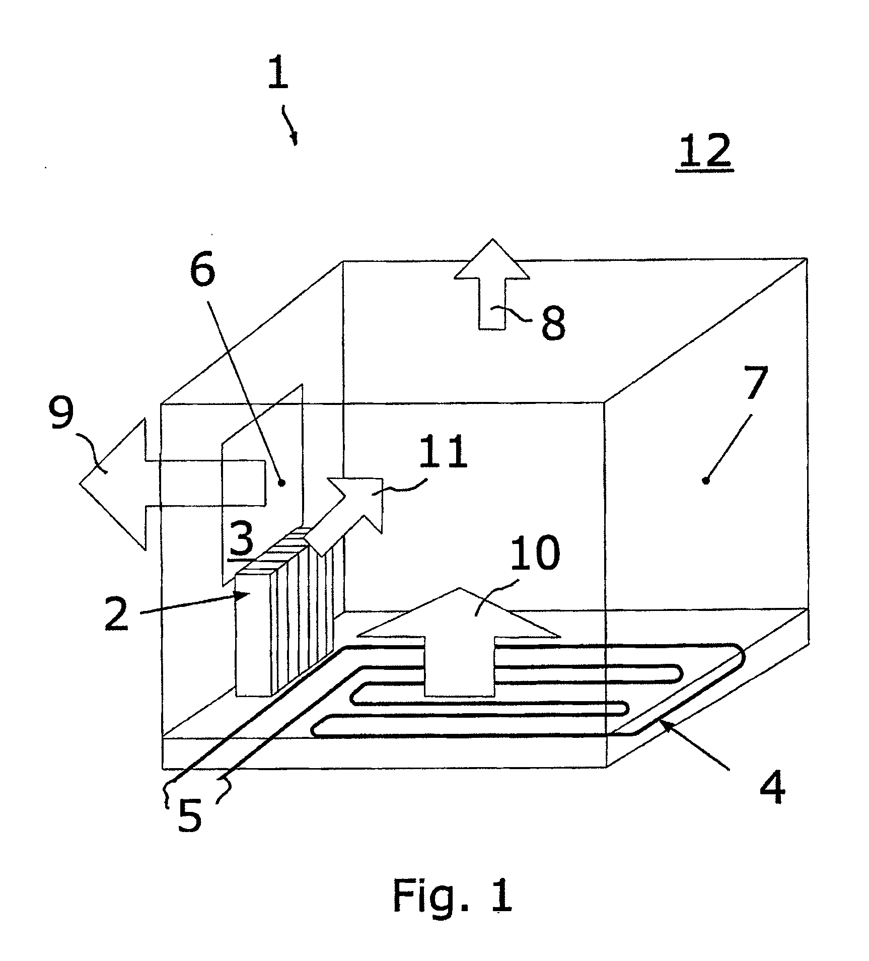
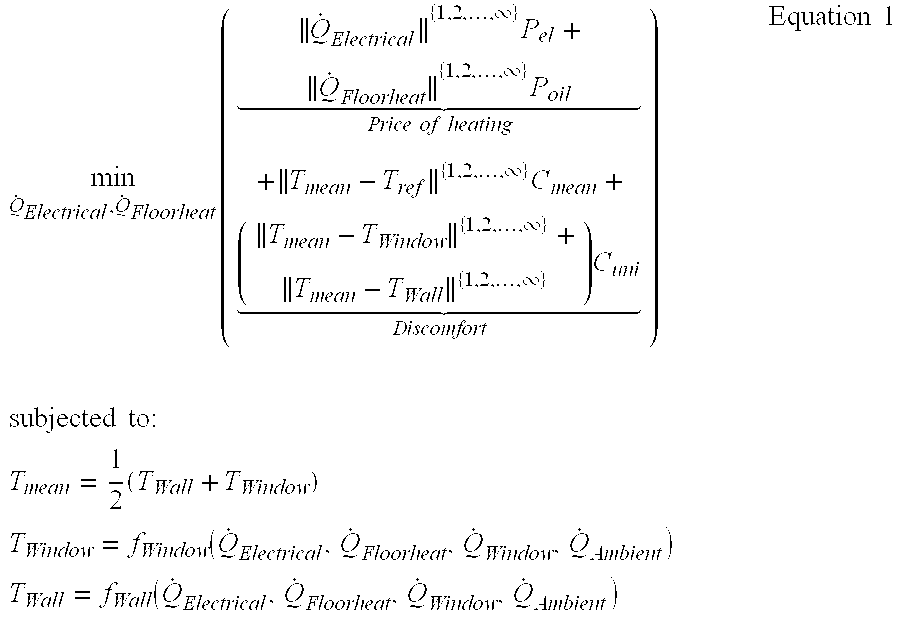
[0006]It is an object of the present invention to improve the indoor climate, and in particular to facilitate an improved control over systems with various sources of thermal energy, e.g. for providing improved comfort, less temperature variations and improved economy. Accordingly, the invention provides a method wherein a comfort criterion and a weight of importance of compliance with the comfort criterion are defined in numerical terms. A supply of a specific amount of energy is considered, with respect to that amount, a numerical expression of a degree of compliance with the comfort criterion, and a numerical expression of costs related to the supply of that amount of energy is provided.

[0007]Since numerical expressions are provided for the degree of compliance with the comfort criterion, the weight of importance of compliance with the comfort criterion and for the costs of supply of the considered amount of energy, an acceptable balance between costs and comfort may be provided....


PUM


Abstract

The invention provides a method for controlling the climate of an environment, e.g. a house, which exchanges thermal energy with an ambient space. Energy is supplied to the environment e.g. by radiators, floor heating, electrical heating fans etc. According to the method, a numerically expressed comfort criteria, and a numerically expressed weight of importance of compliance with the comfort criterion are defined. Subsequently, a supply of a specific amount of energy is considered, and with respect to that amount, a numerical expression of a degree of compliance with the comfort criterion, and a numerical expression of costs related to the supply of that amount of energy are provided.

Description

CROSS REFERENCE TO RELATED APPLICATIONS[0001]This application is entitled to the benefit of and incorporates by reference essential subject matter disclosed in International Patent Application No. PCT / DK2007 / 000059 filed on Feb. 8, 2007 and Danish Patent Application No. PA 2006 00199 filed Feb. 10, 2006.INTRODUCTION[0002]The present invention relates to a method for controlling the climate of an environment which exchanges thermal energy with an ambient space, e.g. for controlling an indoor climate of a building, for controlling a refrigerated space such as a cold store etc. The invention further relates to a system operating in accordance with the method.BACKGROUND OF THE INVENTION[0003]In a house, various heat sources might be installed such as electrical heaters, water based heating systems, HVAC systems etc. These heat sources are characterised by their dissimilarity in influencing the indoor climate and the costs of use. The indoor climate is defined by a huge number of variabl...

Claims


Application Information

Patent Timeline
Patent Type & Authority Applications(United States)
IPC IPC(8): G05B15/00
CPCF24F5/0089F24F11/0017Y02B30/78F24F2011/0094F24F2011/0064F24F11/30F24F2110/50F24F11/65F24F11/47Y02B30/70
Inventor LARSEN, LARS FINN SLOTHTHYBO, HONGLIANTHYBO, CLAUS
Owner DANFOSS AS
Learn More