
Method for laser scanning microscopy and beam combiner

a laser scanning microscopy and beam combiner technology, applied in the field of laser scanning microscopy and beam combiner, can solve the problems of complex and sensitive assembly and adjustment of these components, cost, serviceability, reliability and customer-friendliness, and the inability to implement the legally required laser safety measures. , to achieve the effect of increasing reliability and saving weigh

Inactive Publication Date: 2009-12-10
CARL ZEISS MIKROLMAGING
View PDF15 Cites 2 Cited by
  • Summary
  • Abstract
  • Description
  • Claims
  • Application Information

AI Technical Summary

Benefits of technology

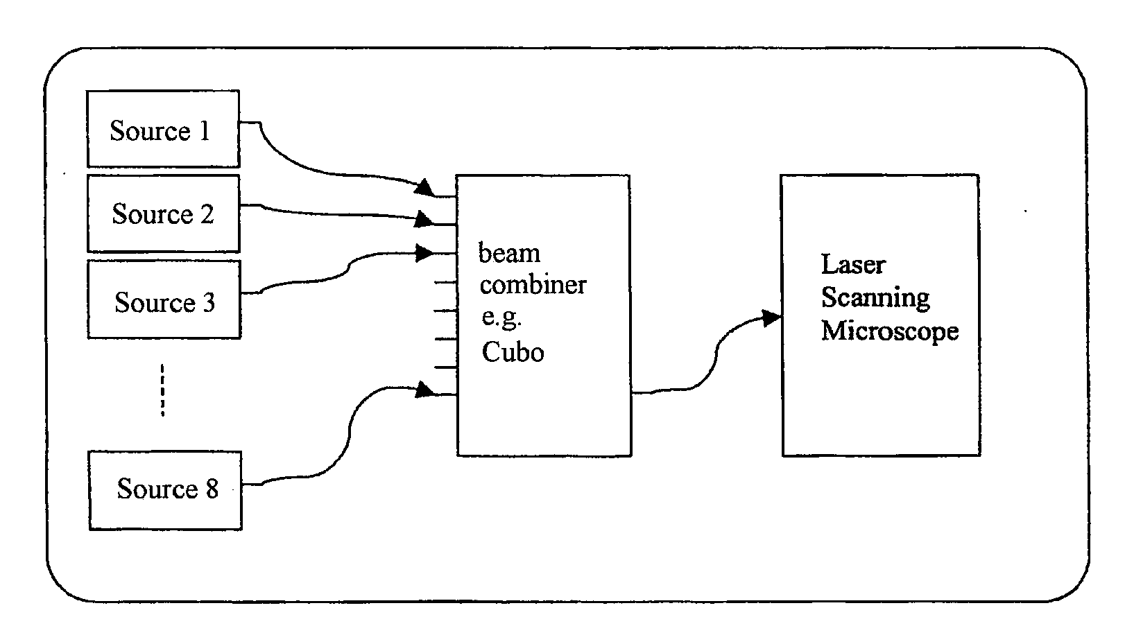
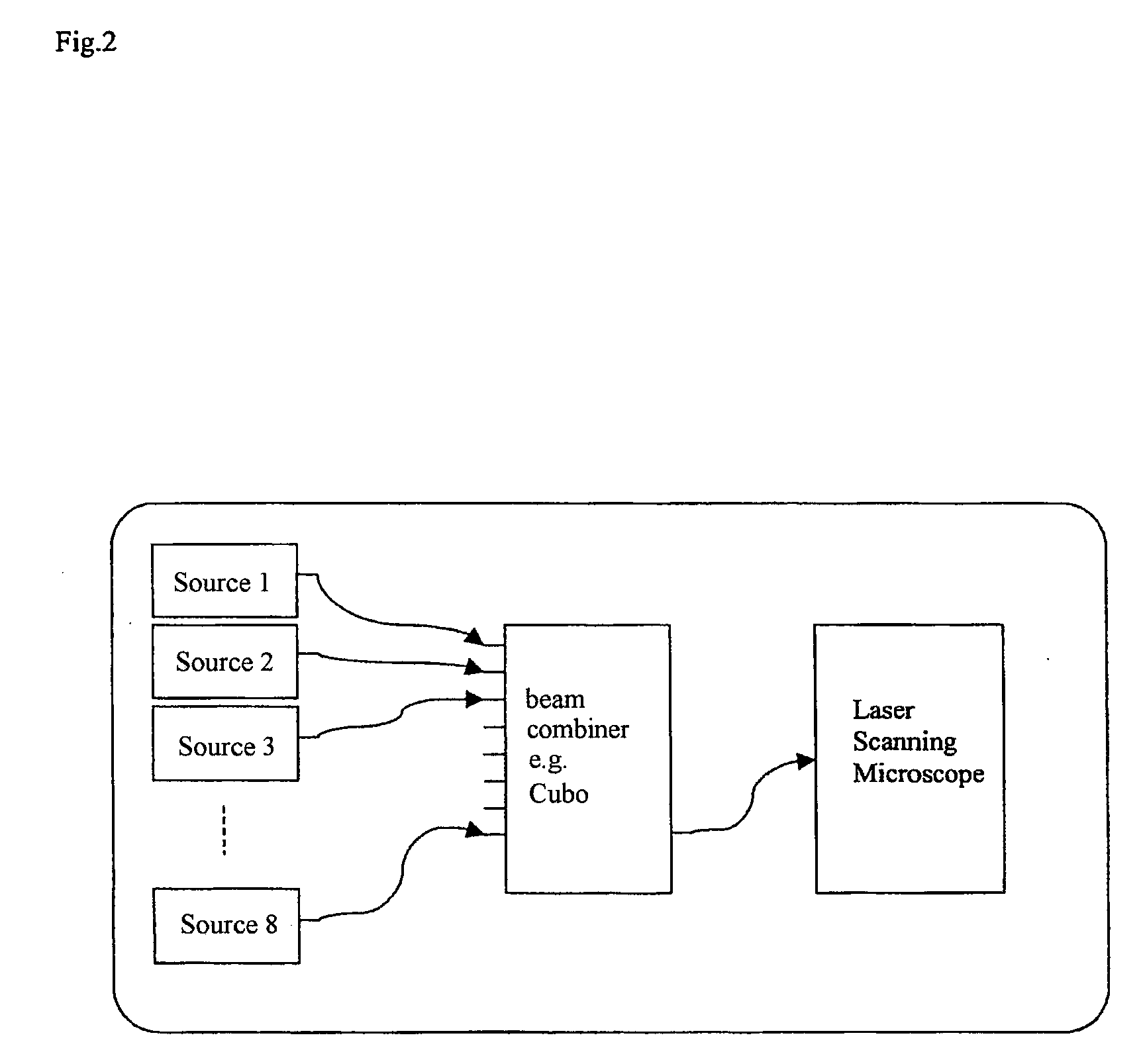
[0020]The invention makes possible a compact construction of a beam combiner for laser scanning microscopy, for example, by means of a Cubo fiber multiplexer or a comparable component. No assembly or adjustment of mirrors and splitters is required. The encapsulated assembly provides for a robust construction which is resistant to environmental influences such as temperature, dust and vibrations and therefore operates with markedly increased in reliability. The considerable savings in weight is also advantageous. The self-contained beam combiner is laser-safe depending on the technology.

Problems solved by technology

The assembly and adjustment of these components is complicated and sensitive.
The environmental influences (temperature, dust, vibrations) to which these assemblies are exposed have a negative impact on performance, production costs, serviceability, reliability and customer-friendliness.
It is also costly to implement the legally required laser safety measures.
Further, the required servicing is time-consuming and expensive due to this complex construction.

Method used


Image

  • Method for laser scanning microscopy and beam combiner
  • Method for laser scanning microscopy and beam combiner
  • Method for laser scanning microscopy and beam combiner

Examples


Embodiment Construction

[0024]It is to be understood that the figures and descriptions of the present invention have been simplified to illustrate elements that are relevant for a clear understanding of the present invention, while eliminating, for purposes of clarity, many other elements which are conventional in this art. Those of ordinary skill in the art will recognize that other elements are desirable for implementing the present invention. However, because such elements are well known in the art, and because they do not facilitate a better understanding of the present invention, a discussion of such elements is not provided herein.

[0025]The present invention will now be described in detail on the basis of exemplary embodiments.

[0026]The invention is shown schematically in FIG. 2. An encapsulated component known from telecommunications, preferably fabricated by TTF thin-film techniques, is suitable for combining the light of, e.g., eight light sources which is guided through fibers and for guiding the...


PUM


Abstract

A method for laser scanning microscopy is characterized by the use of encapsulated fiber multiplexers from the telecommunications field for combining the beams of a plurality of lasers of different wavelengths and coupling them together into a laser scanning microscope and by corresponding beam combiners. Light-conducting guides to which different lasers can be coupled, preferably by light guides, are advantageously guided out of an encapsulated component.

Description

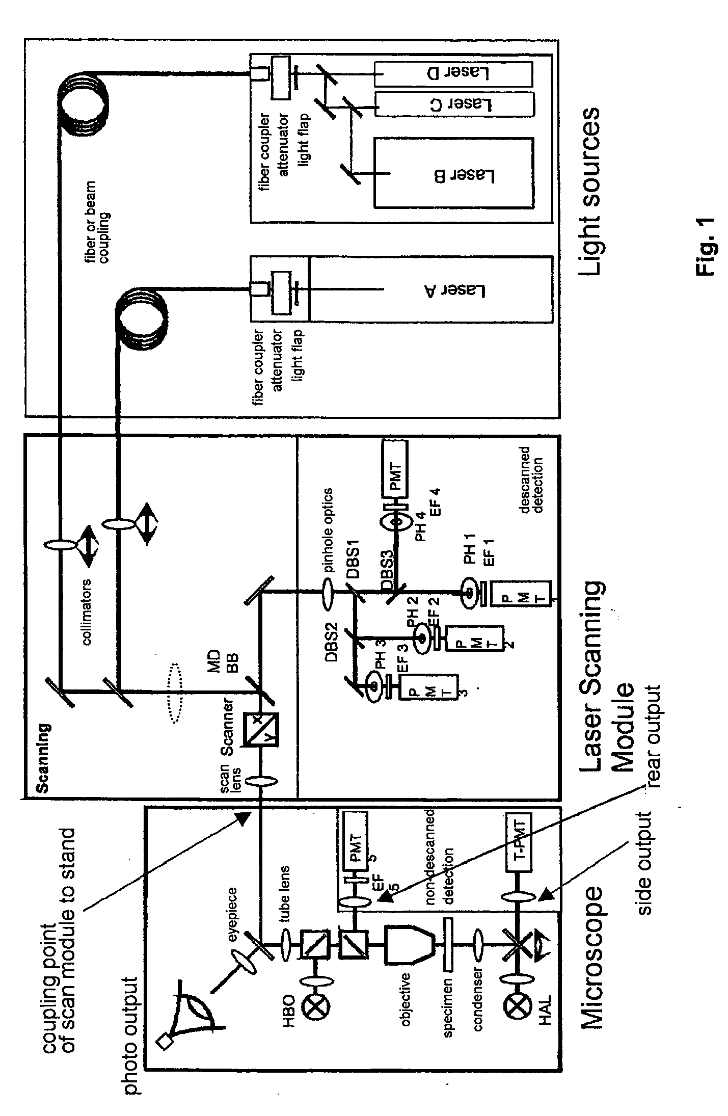
[0001]The present application claims priority from PCT Patent Application No. PCT / EP2007 / 006549 filed on Jul. 24, 2007, which claims priority from German Patent Application No. DE 10 2006 034 909.1 filed on Jul. 28, 2006, the disclosure of which is incorporated herein by reference in its entirety.BACKGROUND OF THE INVENTION[0002]1. Field of the Invention[0003]The invention is directed to a method for laser scanning microscopy involving a beam combiner. The invention presents a compact, encapsulated, completely adjusted assembly containing the beam combiners. The laser sources are coupled in by fibers and are outputted in a combined manner via a fiber. The input fibers and output fibers are fixedly adjusted so that there is no need to adjust a fiber in relation to the beam combiner as in the prior art.[0004]2. Description of the Related Art[0005]Laser scanning systems use lasers of different power classes. Further, a laser scanning system is characterized by a large quantity of varia...

Claims


Application Information

Patent Timeline
IPC IPC(8): G02B21/06G02B27/10
CPCG02B21/002G01N21/6458
Inventor PACHOLIK, JOERGHUHSE, DIETERPAATZSCH, THOMAS
Owner CARL ZEISS MIKROLMAGING
Learn More