
Evaporation element for liquids

a liquid vaporization and liquid technology, applied in the field of liquid vaporization elements, can solve the problems of high energy demand, damage and soot up of the inhalation apparatus, and the battery is impractical, and achieve the effect of small and manageable construction

Active Publication Date: 2009-12-10
STIRZEL ALEXANDER
View PDF5 Cites 15 Cited by
  • Summary
  • Abstract
  • Description
  • Claims
  • Application Information

AI Technical Summary

Benefits of technology

[0007]The present invention is therefore based on the object of providing a vaporization element for liquids which is compact and inexpensive and has diverse uses, in particular for inhalation purposes.
[0009]In the vaporization element according to the invention, the liquid to be vaporized is heated by bringing the liquid itself into contact with the reagent, for example calcium oxide. By actuating the opening element, the film which separates the liquid to be vaporized from the reagent is perforated, so that the liquid reacts with the reagent and heat is released, which causes the liquid to vaporize. Compared with the aerosol vaporization device known from EP 0 371 282 A, the advantage achieved by the invention lies in particular in the simpler, less expensive and more space-saving construction. With the vaporization element present according to the invention, the most space-saving and favourable possibility of providing energy in a portable manner in a small space is utilized, and storage and release by a chemical route.
[0015]The vaporization element with the housing can be so small and manageable in construction that a portable inhalation apparatus which can also be worn e.g. as bracelet, like a watch, results.

Problems solved by technology

However, a high energy demand, which can be satisfied only by a comparatively heavy and voluminous battery, is required for an electrical heat source.
For a portable inhaling apparatus in particular, however, such a battery is impractical, too heavy and too expensive.
External heat sources, such as cigarette lighters or the like, can damage and soot up the inhaling apparatus because of the very high flame temperature and are therefore also not very user-friendly.
Furthermore, handling a naked flame is associated with risks in many respects, and is undesirable because of the combustion products formed.

Method used


Image

  • Evaporation element for liquids
  • Evaporation element for liquids
  • Evaporation element for liquids

Examples


Embodiment Construction

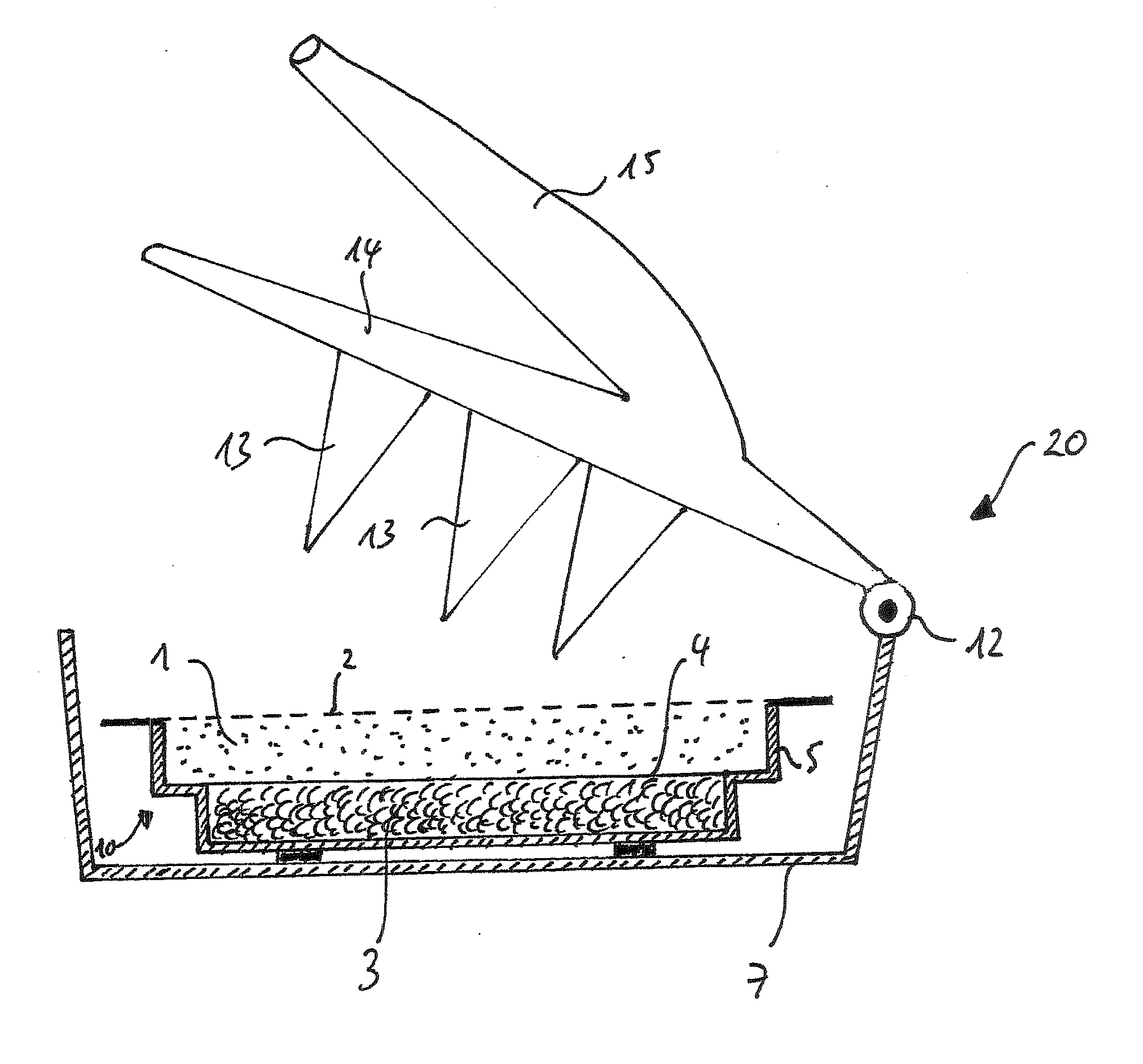
[0020]FIG. 1 shows, in cross-section, an embodiment example of the vaporization element according to the invention without the housing, which is designated overall by the reference number 10. The vaporization element comprises a first upper reservoir 1 which serves as a liquid store for the aqueous solution to be vaporized. The aqueous solution in this context can contain caffeine, nicotine and / or other aroma substances.

[0021]The first reservoir 1 is separated by a thin film of plastic 4 from a second reservoir 3 which contains a reagent, such as, for example, calcium oxide. The first reservoir 1 and the second reservoir 3 are accommodated in a preferably waterproof and heat-resistant trough 5 or a bag, preferably of a heat-resistant film of plastic.

[0022]When the liquid to be vaporized contained in the first reservoir 1 comes into contact with the reagent in the second reservoir 3, the resulting chemical reaction generates sufficient heat to vaporize or to evaporate the liquid with...


PUM


Abstract

An evaporation element for liquids, in particular aqueous solutions, has a first reservoir for storing the liquid that is to be evaporated, a second reservoir, which is separated from the first reservoir by a sheet and contains a reagent that in contact with the liquid that is to be evaporated carries out an exothermic chemical reaction, and an opening element which, on actuation, perforates the sheet and in this way brings the reagent into contact with the liquid that is to be evaporated.

Description

FIELD OF THE INVENTION[0001]The invention relates to a vaporization element for liquids, in particular aqueous solutions, which can contain aromas and, for example, caffeine, nicotine and others, preferably for inhalation of the vaporized liquid.RELATED PRIOR ART[0002]Devices for heating liquids which contain aroma substances, such as, for example, essential oils or the like, for the purpose of inhalation of the liquid vapour impregnated with the aroma substances have been known for a long time.[0003]Medical uses of inhalation of vaporizing liquids lie, for example, in the inhalation of essential oils for alleviating cold symptoms and diseases of the respiratory tract. A further use lies in the administration of nicotine, such as is described in the patent DE 10 2004 033 579 B4. In this context, a mixture of water, nicotine and aroma substances is vaporized, the aroma substances already vaporizing at relatively low temperatures of between 50 and 90° C. Nicotine itself vaporizes only...

Claims


Application Information

Patent Timeline
Patent Type & Authority Applications(United States)
IPC IPC(8): A61M16/10A61M11/00
CPCA61F7/03A61F7/032A61F2007/0062A61M11/041A61M15/0041A61M2205/364A61M11/047A61M15/0035A61M15/00A61M11/042
Inventor STIRZEL, ALEXANDER
Owner STIRZEL ALEXANDER
Learn More