
Applicators and methods for intraoperative treatment of proliferative diseases of the breast

a breast cancer and proliferative disease technology, applied in the field of radiation therapy of proliferative disease, can solve the problems of no applicator, analogous to the balloon applicator, used in special, heavily shielded rooms, and reduce the likelihood of normal tissue being exposed to harmful radiation levels

Active Publication Date: 2009-12-03
XOFT INC
View PDF18 Cites 3 Cited by
  • Summary
  • Abstract
  • Description
  • Claims
  • Application Information

AI Technical Summary

Benefits of technology

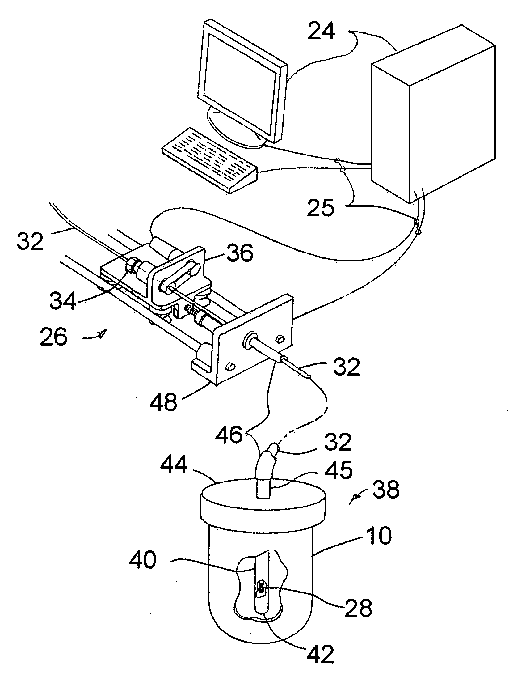
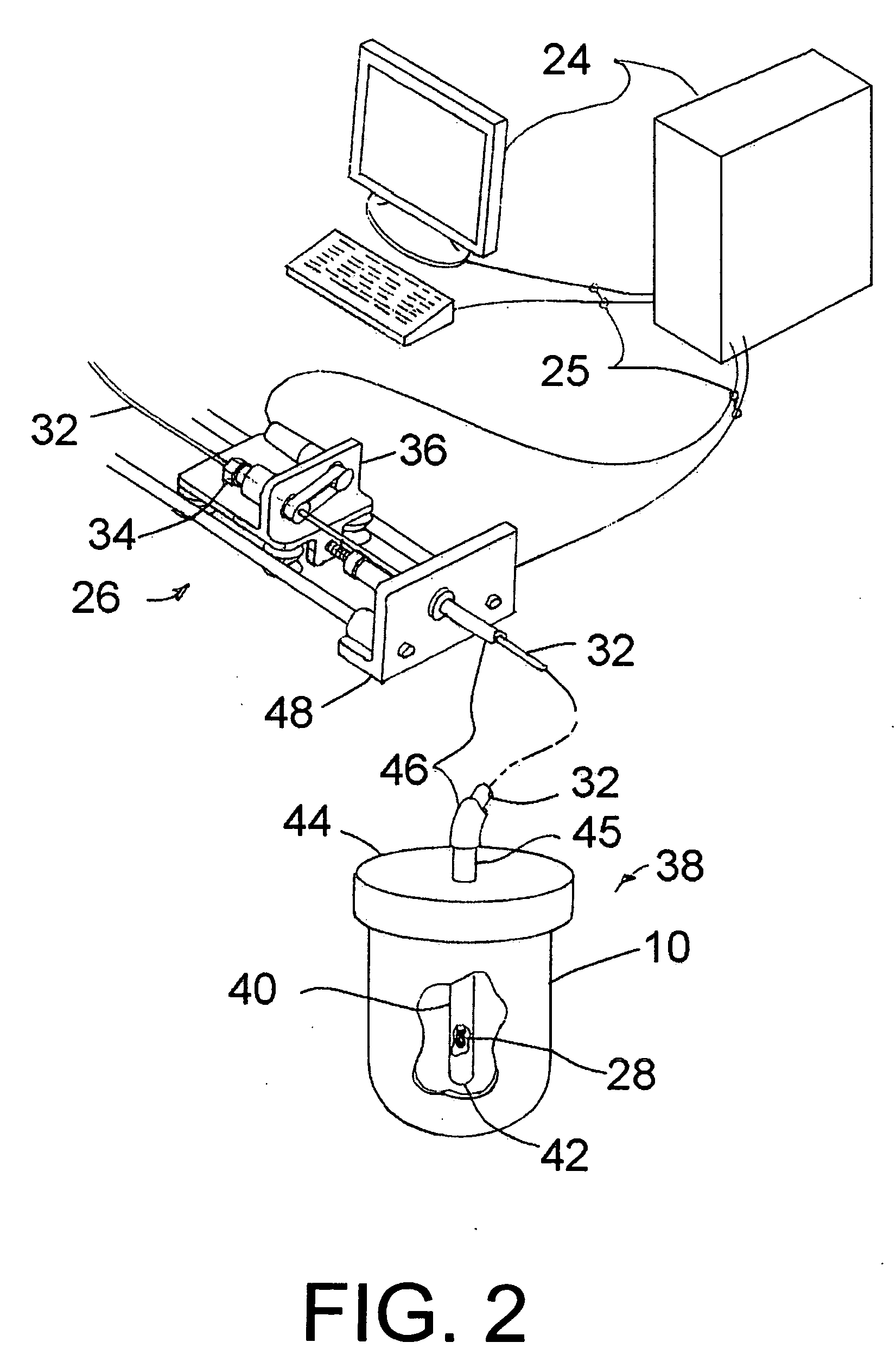
[0010]This invention is intended particularly for the breast and comprises a rigid cup of predetermined shape, the sides of which are transparent to radiation and visible light, and the bottom of which is optionally attenuating in order to shield the underlying tissues and organs from harmful radiation. The cup is placed into the cavity, bottom first, and advanced until it reaches the bottom of the cavity. The cup is configured so as to substantially fill and shape the cavity. If desired, the cup can be sutured near its base to secure it to the bottom of the cavity. After being so placed, the conformance of the cavity tissue to the cup can be visually ascertained, and if necessary adjusted appropriately to eliminate voids or pockets of air or seroma. Alternatively, the surrounding tissue can be urged into conformance with the sides of the cup and held in place by conventional tapes and / or sutures, by selecting a differently shaped rigid cup, or by other methods including provision of a matrix on the outside of the cup for application of suction to draw breast tissue into conformance with the cup and so retain it during radiotherapy.
[0011]The invention further comprises a lid to cover the cup and a connection with a gasket or other conventional features proximate to the cup lip to create a fluid tight seal between the two elements. Near or at the periphery of the lid is a radiation attenuating skirt extending distally into the cup or just outside the cup (with securement threads for engaging the cup) to shield the skin and near-skin tissue gathered around the cup from radiation. If desired, the entire lid (or lid assembly if comprised of multiple elements) can be attenuating to protect those nearby during radiotherapy delivery. Extending through the lid is a tubular source guide which is radiation transparent and reaches sufficiently into the cup such that a radiation source can deliver as therapeutic dose. In one embodiment, the source can be manipulated within the guide (such positioning herein referred to as along the “Z” axis of the applicator or cavity) to effectively deliver the prescribed radiation. The distal end of the source guide is closed. Proximally, the guide extends outward of the lid to an open end where a source and catheter can be inserted. If source manipulation is desired, the proximal end of the source guide further comprises a flexible extension which can be secured to the source manipulator located outside the patient in order to provide a fixed reference distance between the outside manipulation apparatus to the patient and applicator. Such a flexible connection can accommodate patient motion, for example motion due to respiration, without introducing error in source positioning.

Problems solved by technology

This reduces the likelihood of exposing normal tissue to harmful levels of radiation, particularly that tissue nearest the radiation source, while still delivering the prescribed radiation to the prescribed depth.
At present, however, there are no applicators, analogous to the balloon applicators described above, for use with IORT methods in open surgical fields.
They also emit continuously, and thus can only be used in special, heavily-shielded rooms.
In total, the capital expense required for such facilities dictates that treatment centers be located in urban areas so as to serve sizeable patient populations.
This can result in under serving rural patients who cannot repeatedly travel to urban treatment centers for a course of prolonged radiation treatment.
Furthermore, the need for patient isolation is inconvenient for therapists, not to mention daunting for the patients under treatment.
Isotope radiation cannot be controlled in this manner.

Method used


Image

  • Applicators and methods for intraoperative treatment of proliferative diseases of the breast
  • Applicators and methods for intraoperative treatment of proliferative diseases of the breast
  • Applicators and methods for intraoperative treatment of proliferative diseases of the breast

Examples


Embodiment Construction

[0022]FIG. 1 shows in section view, a preferred brachytherapy applicator cup 10 positioned in an open surgical cavity 12 left in the breast 14 of a patient following (at least partial) tumor resection. The cup preferably is substantially rigid, of a predetermined shape (in this example circular), and preferably substantially transparent to x-rays and to visible light, or at least partially transparent to x-rays. It may, for example, be molded from engineering plastic, preferably with a specific gravity near unity to simplify treatment planning. Suitable materials would include polycarbonate, polyphenolene ether (Noryl, from GE Plastics, is an example) and polyethersulfone (Radel, from Solvay Advanced Polymers is another example). The shape can be generally circular-cylindrical, or other shapes.

[0023]If the tissues at the bottom of the cavity are susceptible to radiation damage and are to be protected, the material of the bottom portion 16 of the cup may further comprise the addition...


PUM


Abstract

A device for administering brachytherapy to a patient includes a vessel that may be in the form of a hollow cylindrical cup, for fleshing into and substantially filling the open-ended cavity. The vessel has a closed outer end, which may be a removable cover, and a source guide penetrates the closed outer end so as to extend deep into the vessel, to receive a radiation source in the source guide. A manipulator can be connected to the radiation source, and also to the source guide, for allowing several different types of manipulation of the source orientation and position within the vessel during the brachytherapy procedure.

Description

BACKGROUND OF THE INVENTION[0001]This invention relates to radiation therapy of proliferative disease as required adjuvant care following surgical resection of tumors or other pathological conditions. More particularly, it pertains to the intraoperative application of therapeutic radiation emitted from radiation sources positioned within the resection cavity created by surgical resection. Discussion herein is largely directed to radiotherapy following at least partial resection of breast tumors, but it is to be understood that the apparatus and methods may be applied to different anatomical sites.[0002]It has been demonstrated in many areas of surgical oncology that adjuvant radiation treatment following tumor resection reduces the likelihood of recurrence of cancer or other proliferative disease. The likelihood of infiltrative disease decreases with distance from a primary site in a tissue with confirmed disease. It has also been shown that brachytherapy delivered from within the r...

Claims


Application Information

Patent Timeline
IPC IPC(8): A61M36/04
CPCA61N5/1015A61N5/1083A61N5/1043
Inventor FRANCESCATTI, DARIUSJERVIS, JAMES E.
Owner XOFT INC
Learn More