Capacitor structure and metal layer layout thereof

a capacitor and metal layer technology, applied in capacitors, semiconductor devices, semiconductor/solid-state device details, etc., can solve the problems of unit capacitance and plugs are limited to the periphery of electrodes, and achieve the effect of higher unit capacitance and better capacitance characteristics

Inactive Publication Date: 2009-12-03
MEDIATEK INC
View PDF11 Cites 7 Cited by
  • Summary
  • Abstract
  • Description
  • Claims
  • Application Information

AI Technical Summary

Benefits of technology

[0009]It is therefore one of the objectives of the present invention to provide a capacitor structure with better capacitance characteristics and a higher unit capacitance.

Problems solved by technology

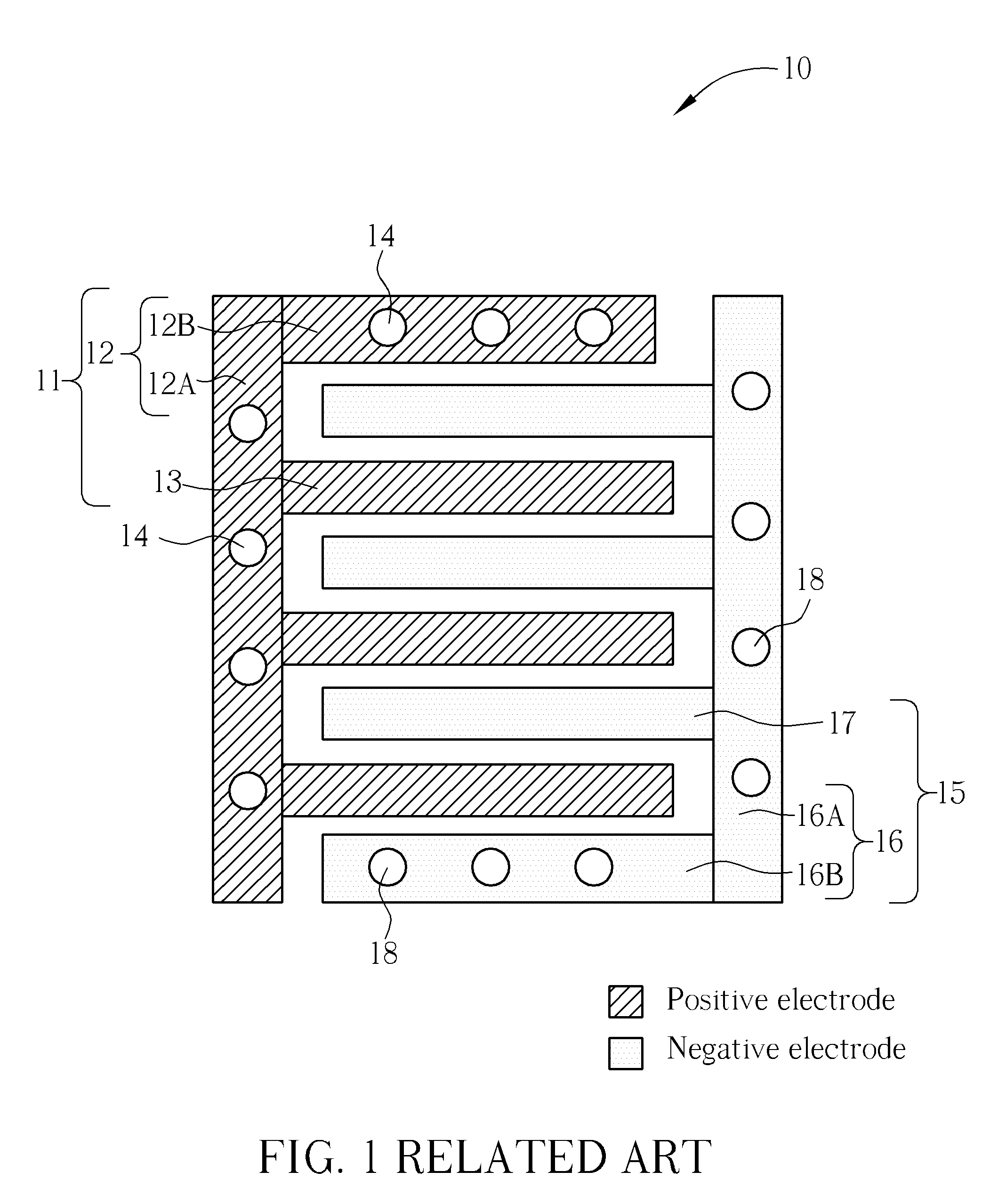
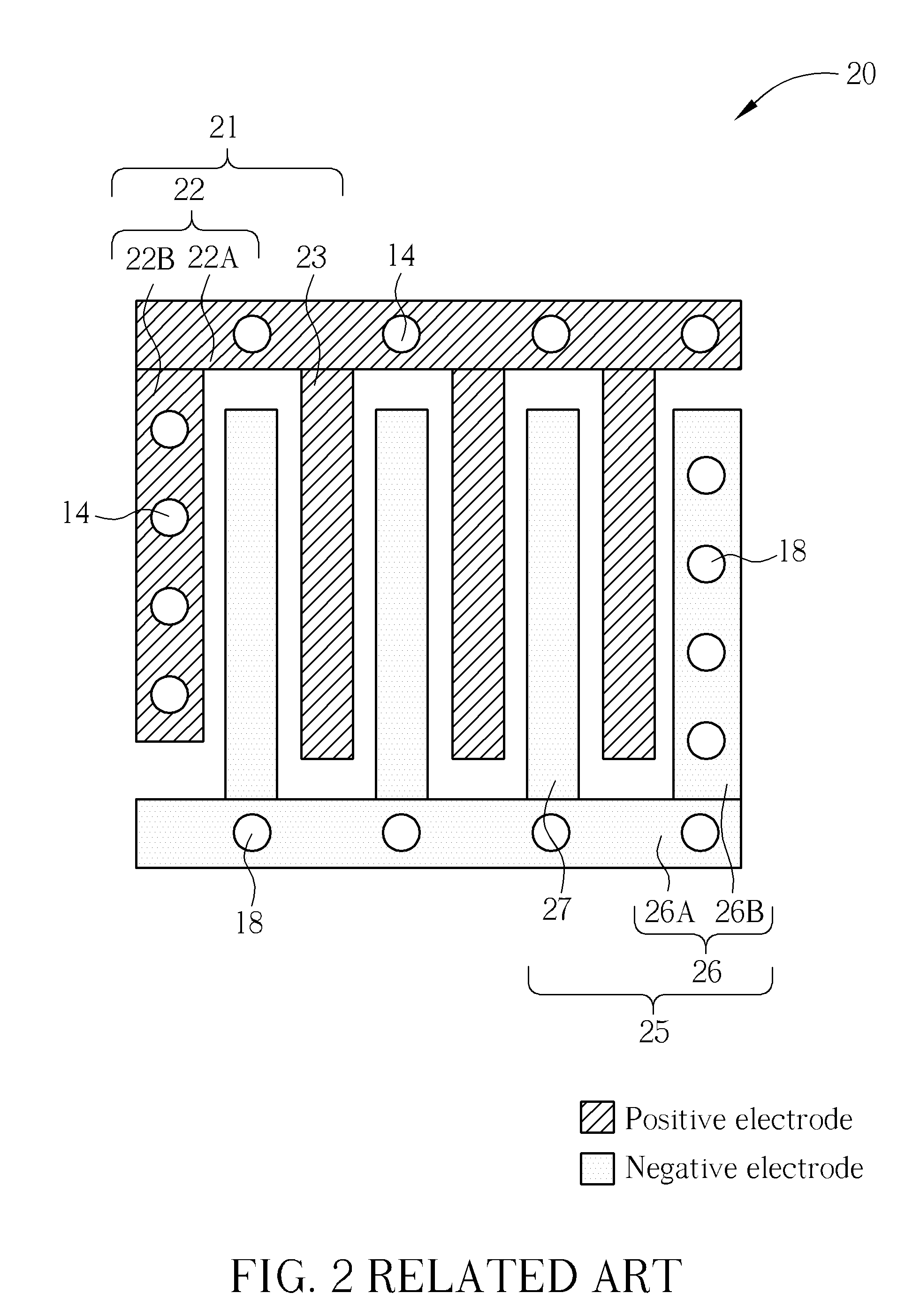
However, although the electrical connection between the part of an electrode in the odd layer and the part of the same electrode in the even layer is formed with the via plugs in the interdigitated capacitor structure with a plurality of metal layers in the U.S. Pat. No. 6,819,542, the locating positions of the via plugs are limited to the periphery of electrodes, and this condition results in a smaller unit capacitance for the interdigitated capacitor structure in the U.S. Pat. No. 6,819,542.

Method used


Image

  • Capacitor structure and metal layer layout thereof
  • Capacitor structure and metal layer layout thereof
  • Capacitor structure and metal layer layout thereof

Examples


Embodiment Construction

[0023]Certain terms are used throughout the following description and the claims to refer to particular system components. As one skilled in the art will appreciate, manufacturers may refer to a component by different names. This document does not intend to distinguish between components that differ in name but not function. In the following discussion and in the claims, the terms “include”, “including”, “comprise”, and “comprising” are used in an open-ended fashion, and thus should be interpreted to mean “including, but not limited to . . . ” The terms “couple” and “coupled” are intended to mean either an indirect or a direct electrical connection. Thus, if a first device couples to a second device, that connection may be through a direct electrical connection, or through an indirect electrical connection via other devices and connections. In addition, the term “strip” or “strips” used in the present invention can be any elongated shape.

[0024]Please refer to FIG. 3 and FIG. 4 at th...


PUM


Abstract

A capacitor structure includes: a first metal layer including: a first frame structure including a first main frame and at least a first frame strip coupled to the first main frame for separating the first main frame to a plurality of first frame sections; and a plurality of first strips, each of the plurality of first strips positioned and isolated in one of the plurality of first frame sections; a second metal layer including: a second frame structure including a second main frame and at least a second frame strip coupled to the second main frame for separating the second main frame to a plurality of second frame sections; and a plurality of second strips, each of the plurality of second strips positioned and isolated in one of the plurality of second frame sections; and a dielectric layer, formed between the first metal layer and the second metal layer.

Description

BACKGROUND[0001]The present invention relates to a capacitor structure and a metal layer layout thereof, and more particularly, to a metal-oxide-metal (MOM) type capacitor structure and a metal layer layout thereof.[0002]Capacitors are critical components in the integrated circuit devices of today. Large value capacitors are useful in analog circuits or radio frequency (RF) circuits such as those designed for filtering or signal processing. Due to trends toward higher levels of integration, it is desirable to integrate large value capacitors onto integrated circuit devices, and various types of integrated capacitors have been devised. For example, metal-oxide-metal (MOM) capacitors have been increasing in popularity because their minimal capacitive loss to the substrate results in a high-quality capacitor.[0003]Applications of interdigitated metal capacitors have already been disclosed and discussed in various literature, such as U.S. Pat. No. 4,409,608, U.S. Pat. No. 5,208,725, U.S...

Claims


Application Information

Patent Timeline
Patent Type & Authority Applications(United States)
IPC IPC(8): H01G4/06
CPCH01L28/60H01L23/5223H01L2924/0002
Inventor CHIU, CHIH-JUNGCHEN, WEN-LIN
Owner MEDIATEK INC
Why Eureka
Try Eureka