
Microchip And Method Of Using The Same

a microchip and chip technology, applied in the field of microchips, can solve problems such as inaccurate test/analysis, and achieve the effects of high efficiency, hindering test/analysis, and highly reliabl

Inactive Publication Date: 2009-11-26
ROHM CO LTD
View PDF12 Cites 6 Cited by
  • Summary
  • Abstract
  • Description
  • Claims
  • Application Information

AI Technical Summary

Benefits of technology

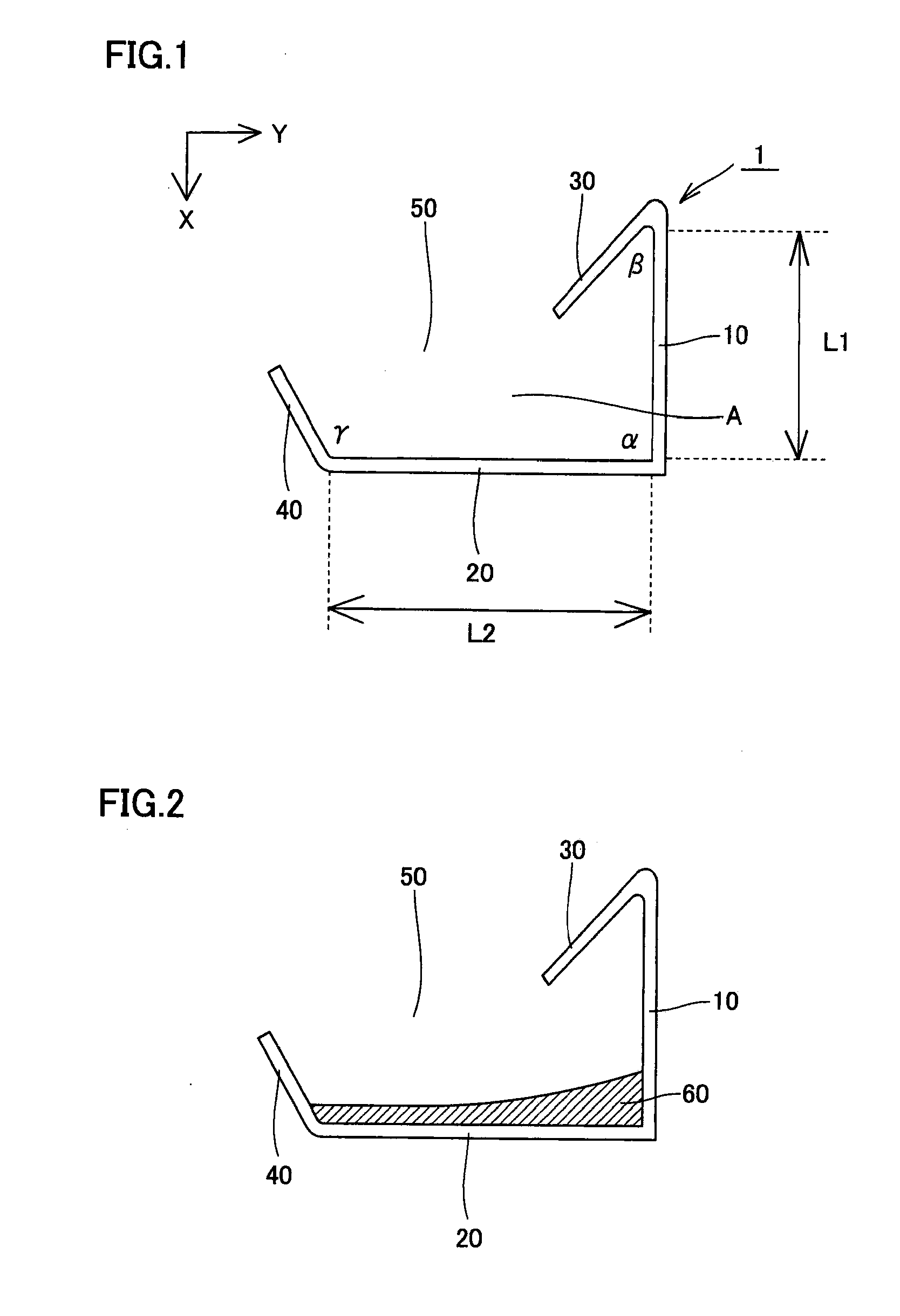
[0008]A first object of the present invention is to provide a microchip including a mixing portion having superior mixing efficiency allowing highly efficient mixing of two or more different types of liquids (typically, a specimen or a specific component of the specimen and one or more liquid reagents) of a relatively simple structure, as well as to provide a method of using the microchip.
[0010]Therefore, a second object of the present invention is to provide a microchip by which a plurality of different types of liquid reagents can be mixed separately with the specimen or the specific component of the specimen and by which accuracy of test and analysis can further be improved.
[0016]Preferably, the residue separating portion has an approximately V-shaped wall; and one of two walls forming the approximately V-shaped wall has such a length that prevents the supernatant and the residue from flowing out from the residue separating portion when centrifugal force in the first direction is applied and allows only the supernatant to flow out from the residue separating portion when centrifugal force in the second direction is applied.
[0018]By the microchip in accordance with the present invention, two or more different liquids, for example, the specimen or the specific component of the specimen and one or more liquid reagents, can be mixed with high efficiency. Therefore, in the microchip, a liquid mixture sufficiently mixed and subjected to appropriate treatment or reaction as intended can be obtained and, hence, highly reliable and accurate test / analysis becomes possible.

Problems solved by technology

If mixing is insufficient, the treatment to be done on the specimen or the specific component of the specimen by the liquid reagent would be insufficient, or reaction between the specimen or the specific component of the specimen and the liquid reagent would be insufficient, possibly resulting in inaccurate test / analysis.

Method used


Image

  • Microchip And Method Of Using The Same
  • Microchip And Method Of Using The Same
  • Microchip And Method Of Using The Same

Examples


first embodiment

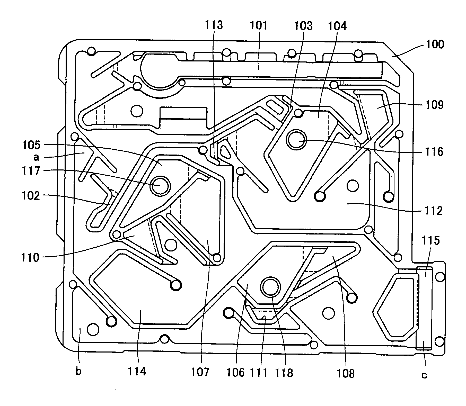
[0028]The microchip in accordance with the present embodiment allows various chemical synthesis, test / analysis and the like using its fluid circuit. In a preferred example, the microchip in accordance with the present embodiment includes a second substrate and a first substrate stacked on and joined to the second substrate. More specifically, on the second substrate, the first substrate having a groove on its surface is joined such that the surface having the groove formed thereon of the first substrate faces the second substrate. Therefore, the microchip consisting of two substrates as such has a fluid circuit composed of a cavity by the groove formed on the surface of first substrate and that surface of the second substrate which faces the first substrate. Though the shape and pattern of the groove formed on the surface of first substrate are not specifically limited, these are determined such that the structure of cavity formed by the groove and the surface of second substrate re...

second embodiment

[0063]The microchip in accordance with the present embodiment will be described, with reference to a preferred example. In the following, mainly the characteristic portions of the microchip in accordance with the present embodiment will be described. Other structures are the same as in the first embodiment. A preferred example of the microchip in accordance with the present embodiment is the same as the microchip shown in FIG. 4.

[0064]FIG. 5 is a schematic top view showing a preferred example of the microchip in accordance with the present embodiment. FIG. 6 is a schematic top view showing, in enlargement, a portion of FIG. 5.

[0065]A microchip 500 shown in FIG. 5 is formed by stacking a second substrate to a surface having a groove thereon of the first substrate, which has a groove forming the fluid circuit on its surface and a through hole passing through its thickness direction. FIG. 5 is a top view showing the surface on the side of first substrate, of such a microchip 500. Actua...


PUM

PropertyMeasurementUnit
inner angleaaaaaaaaaa

Abstract

A microchip is provided, which includes: a second substrate, and a first substrate having a groove on its surface, stacked on the second substrate; and a fluid circuit composed of a cavity defined by the groove and a surface of the second substrate on the side of the first substrate; wherein the fluid circuit includes a mixing portion as a chamber for mixing two or more liquids; and at least a part of a wall forming the mixing portion consists of a linearly extending first wall and a second wall linearly extending from an end of the first wall. A method of using the microchip is also provided.

Description

BACKGROUND OF THE INVENTION[0001]1. Field of the Invention[0002]The present invention relates to a microchip useful as a μ-TAS (Micro Total Analysis System) used for environmental analysis, chemical synthesis and biochemical test of DNA, protein, cells, immunity, blood and the like as well as to a method of using the microchip.[0003]2. Description of the Background Art[0004]Recently, in the field of medical, health, food and drug discovery, importance of sensing, detecting and estimating quantity of chemical substance and biological matter such as DNA (Deoxyribo Nucleic Acid), enzyme, antigen, antibody, protein, viruses and cells has been increasing, and various biochips and micro chemical chips (hereinafter generally referred to as microchips) allowing easy examination of these have been proposed. The microchip enables a series of experiments / analysis operations, which has been conducted in a laboratory, within a chip having the size of a few centimeters to ten centimeters square a...

Claims


Application Information

Patent Timeline
Patent Type & Authority Applications(United States)
IPC IPC(8): G01N33/00B01L3/00
CPCB01F13/0059B01F15/0203B01F15/0233B01L3/50273B01L2200/04B01L2200/10G01N33/491B01L2300/0816B01L2300/0819B01L2300/087B01L2400/0409G01N21/07B01L2200/12B01F33/30B01F35/712B01F35/71725
Inventor AOKI, YOUICHI
Owner ROHM CO LTD
Learn More