
Method for optimizing a multilevel filter bank and corresponding filter bank and hearing apparatus

a filter bank and multi-level technology, applied in the field of multi-level filter banks and corresponding filter banks and hearing apparatuses, can solve the problems of ineffective hearing aid elimination methods, sampling rate cannot be reduced to the extent of interference from spectral aliasing, etc., to achieve the effect of reducing the delay of the time, reducing the interference, and increasing the signal manipulation

Active Publication Date: 2009-11-26
SIVANTOS PTE LTD
View PDF1 Cites 10 Cited by
  • Summary
  • Abstract
  • Description
  • Claims
  • Application Information

AI Technical Summary

Benefits of technology

The patent text describes a method for optimizing the structure of a multilevel filter bank used in hearing devices. The method involves determining the group delay and operation rate of each filter bank, selecting the optimal filter bank based on these parameters, and configuring the input-side and output-side filter banks accordingly. The optimized filter bank system has improved performance, including reduced interference and improved resolution. The method can be used with various hearing devices, such as hearing aids and cochlear implants. The use of an NPR filter bank can further improve the performance of the hearing device.

Problems solved by technology

Conventional methods of eliminating aliasing are not effective in hearing aids because of the intensive sub-band processing (in particular the high level of amplification required to compensate for the hearing loss).
In particular, the group delay must be kept as low as possible for high frequencies, which is a crucial limiting factor for the filter bank.
However, the sampling rate can only be reduced to the extent that interference from spectral aliasing is not produced by manipulation of the sub-band signals.

Method used


Image

  • Method for optimizing a multilevel filter bank and corresponding filter bank and hearing apparatus
  • Method for optimizing a multilevel filter bank and corresponding filter bank and hearing apparatus
  • Method for optimizing a multilevel filter bank and corresponding filter bank and hearing apparatus

Examples


Embodiment Construction

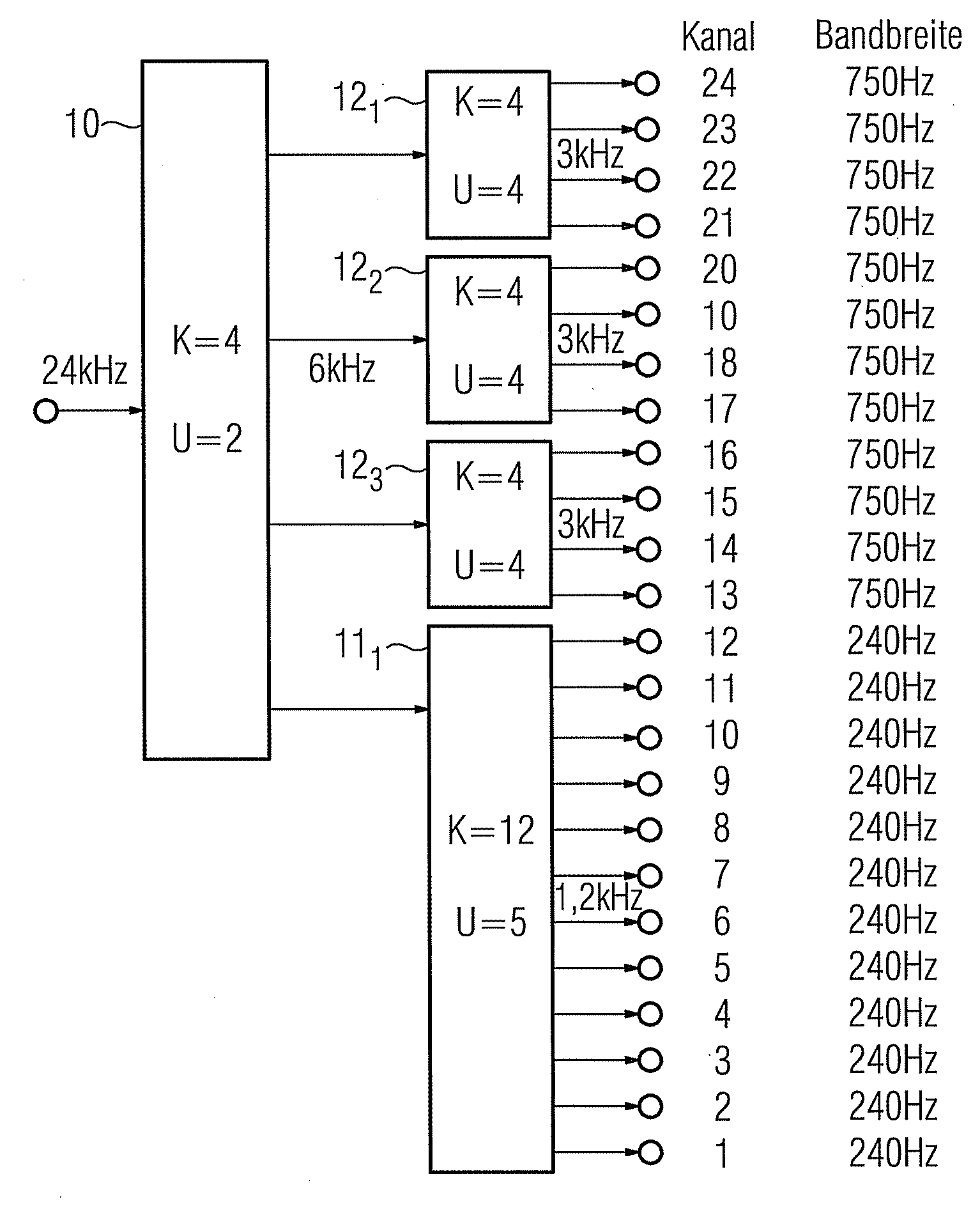
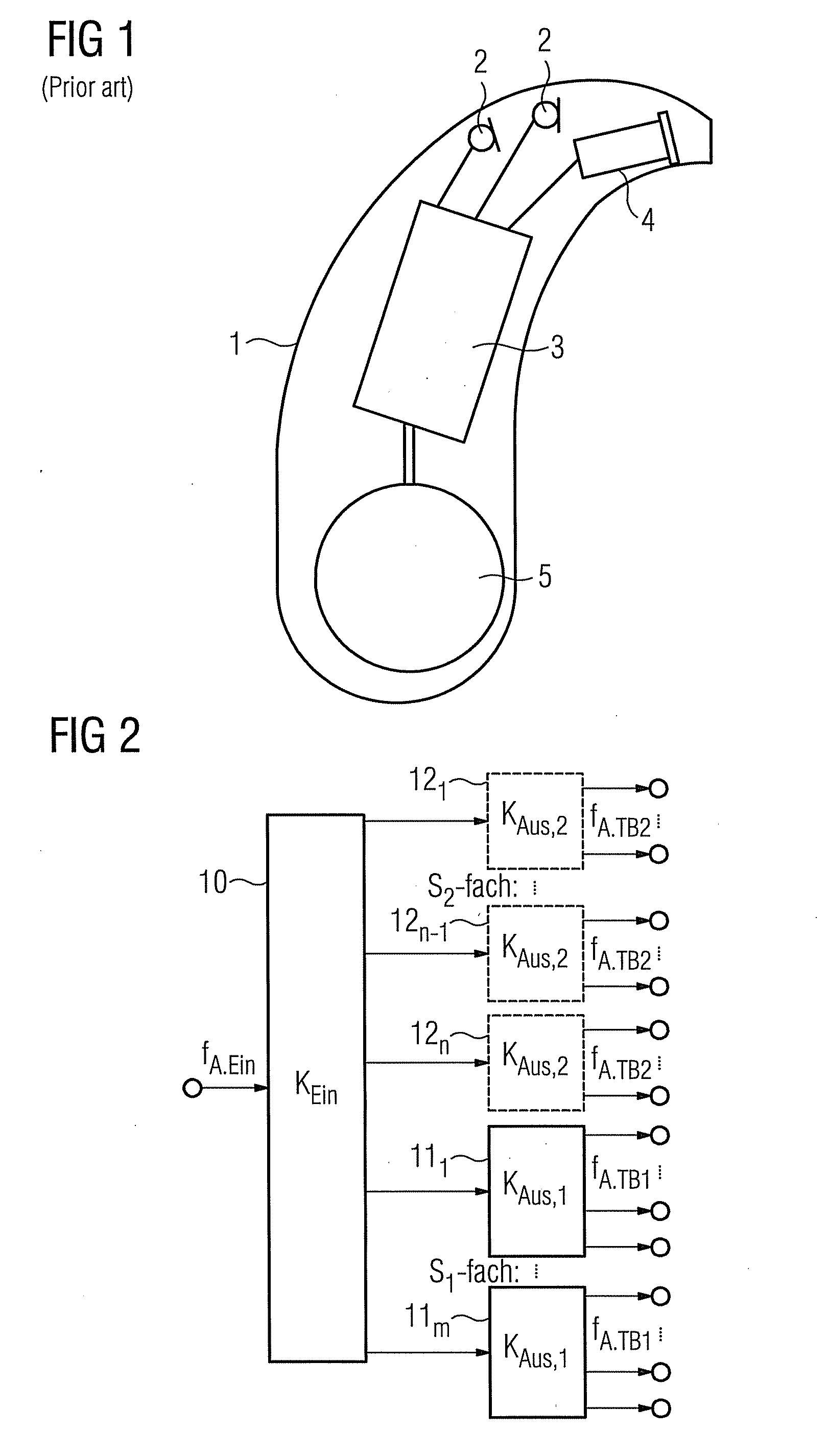
[0028]The embodiments described in greater detail below constitute preferred exemplary embodiments of the present invention. In the following example, a tree structure of a filter bank design as shown in FIG. 2 is used as the basis for the optimization method according to the invention. Such a basic filter bank design comprises an input-side filter bank 10 and a plurality of output-side filter banks 111 to 11m and 121 to 12n. The number of channels KEin in the input-side filter bank 10 is given by KEin=n+m. The sampling rate at the input of the filter bank 10 equals fA,Ein.

[0029]The basic filter bank design contains simply two levels in this example. Hence, apart from the input-side filter bank 10 in the first level, it only has a second level containing the filter banks 111 to 11m and 121 to 12n, each of which constitute conventional complex modulated filter banks. The number of useful-data channels in the filter banks 111 to 11m equals KAus,1, while the number of useful-data chann...


PUM


Abstract

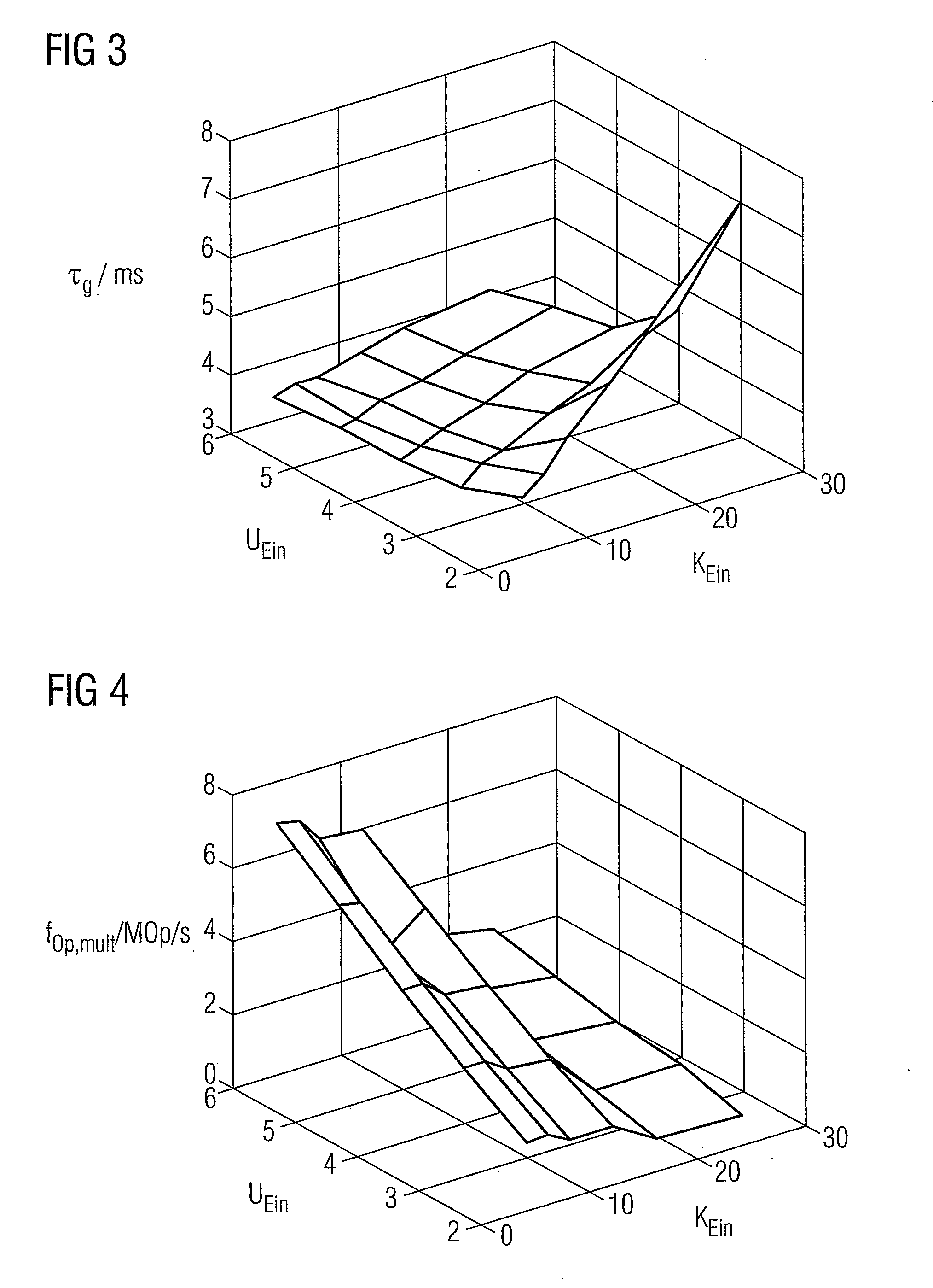
A filter bank system that is optimized with respect to group delay and power consumption is provided. The filter bank system has multiple levels and has an input-side and an output-side filter bank based on a defined filter type. The input-side filter bank has input channels as a variable first parameter, and an oversampling factor as a variable second parameter. For optimizing the multilevel filter bank, a group delay and an operation rate are now respectively determined for each of a plurality of value pairs of the first and second parameters. The value pair for which the associated group delay and the associated operation rate satisfy a defined criterion, in particular for which they are as low as possible, is selected from the value pairs. The input-side filter bank is subsequently configured with the number of channels and the oversampling factor corresponding to the selected value pair.

Description

CROSS REFERENCE TO RELATED APPLICATIONS[0001]This application claims priority of German application No. 10 2008 024 535.6 DE filed May 21, 2008, which is incorporated by reference herein in its entirety.FIELD OF INVENTION[0002]The present invention relates to a method for optimizing a structure of a multilevel filter bank, which has an input-side and an output-side filter bank based on a defined filter type, with the input-side filter bank having the number of input channels as a variable first parameter, and an oversampling factor as a variable second parameter. In addition, the present invention relates to a multilevel filter bank whose structure is obtained using an above method. The present invention also relates to a hearing apparatus containing such a multilevel filter bank. The term “hearing apparatus” is understood to mean here any sound-emitting device that can be worn in or on the ear, in particular a hearing aid, a headset, earphones and the like.BACKGROUND OF INVENTION[0...

Claims


Application Information

Patent Timeline
Patent Type & Authority Applications(United States)
IPC IPC(8): H04R25/00
CPCH03H17/0266
Inventor ALFSMANN, DANIEL
Owner SIVANTOS PTE LTD
Learn More