
Liquid crystal display device, liquid crystal display method, and television receiver

a liquid crystal display and liquid crystal technology, applied in the field of liquid crystal display devices, liquid crystal display methods, television receivers, etc., to achieve the effect of high quality

Inactive Publication Date: 2009-11-19
SHARP KK
View PDF13 Cites 13 Cited by
  • Summary
  • Abstract
  • Description
  • Claims
  • Application Information

AI Technical Summary

Benefits of technology

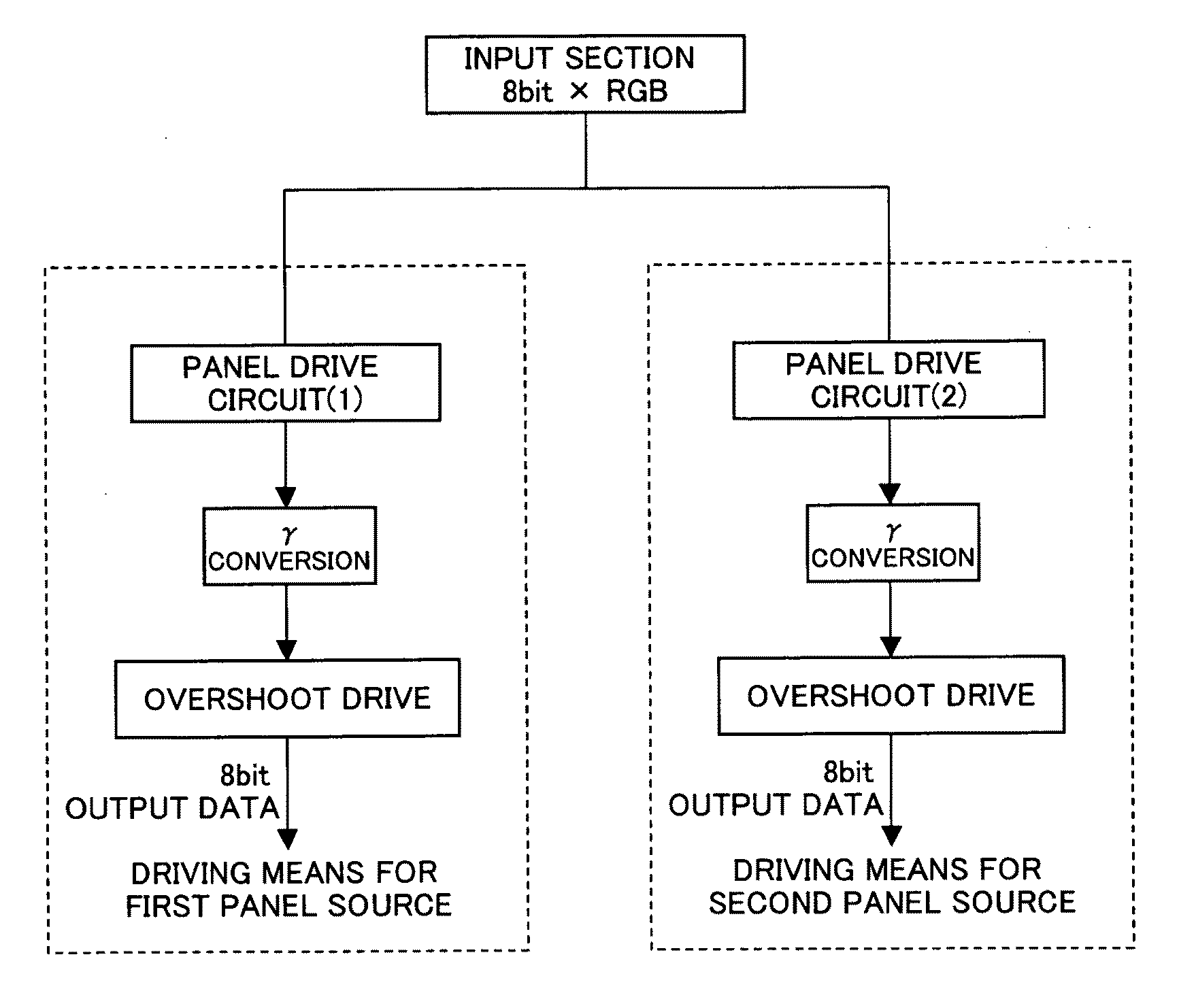
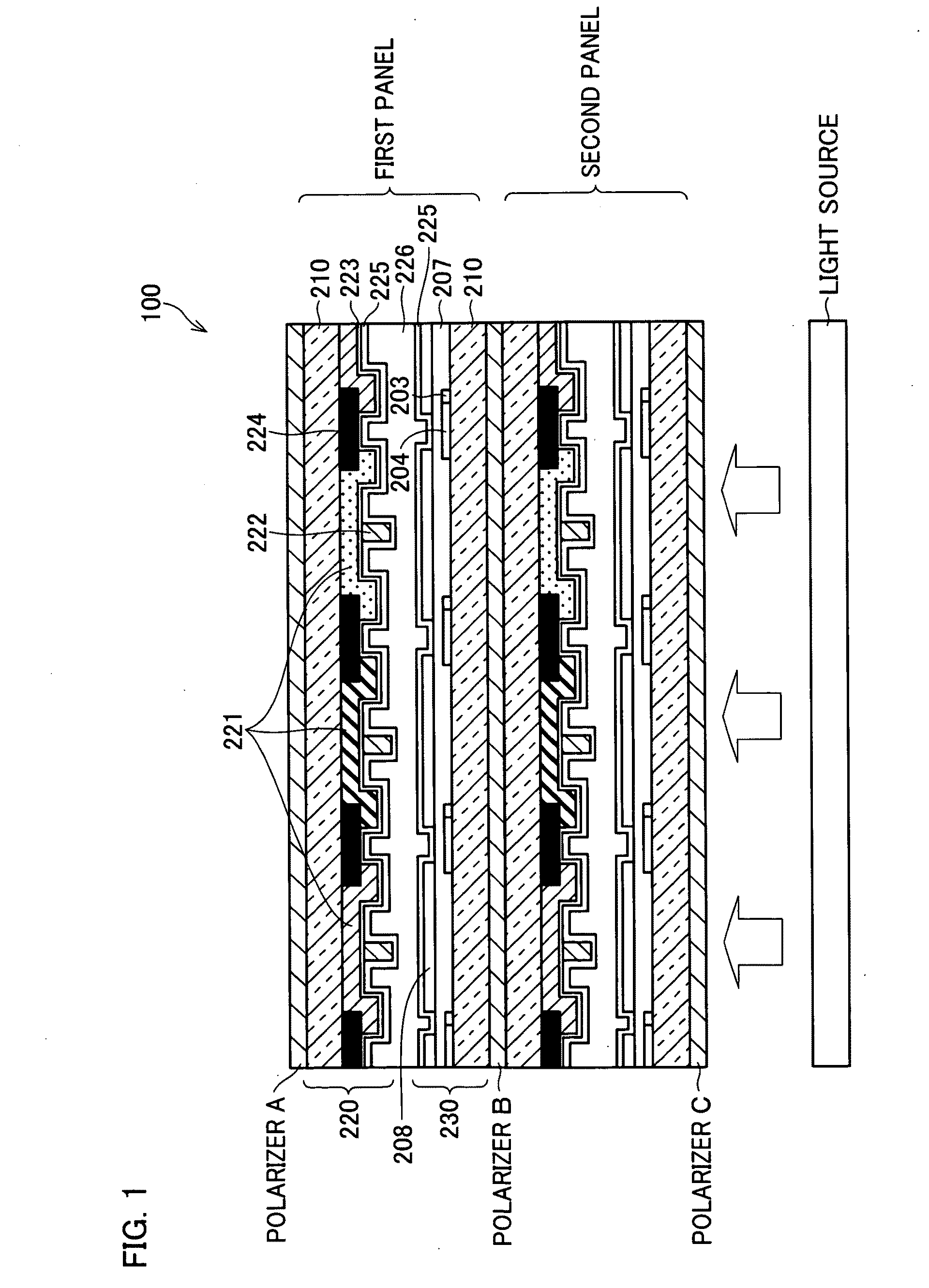
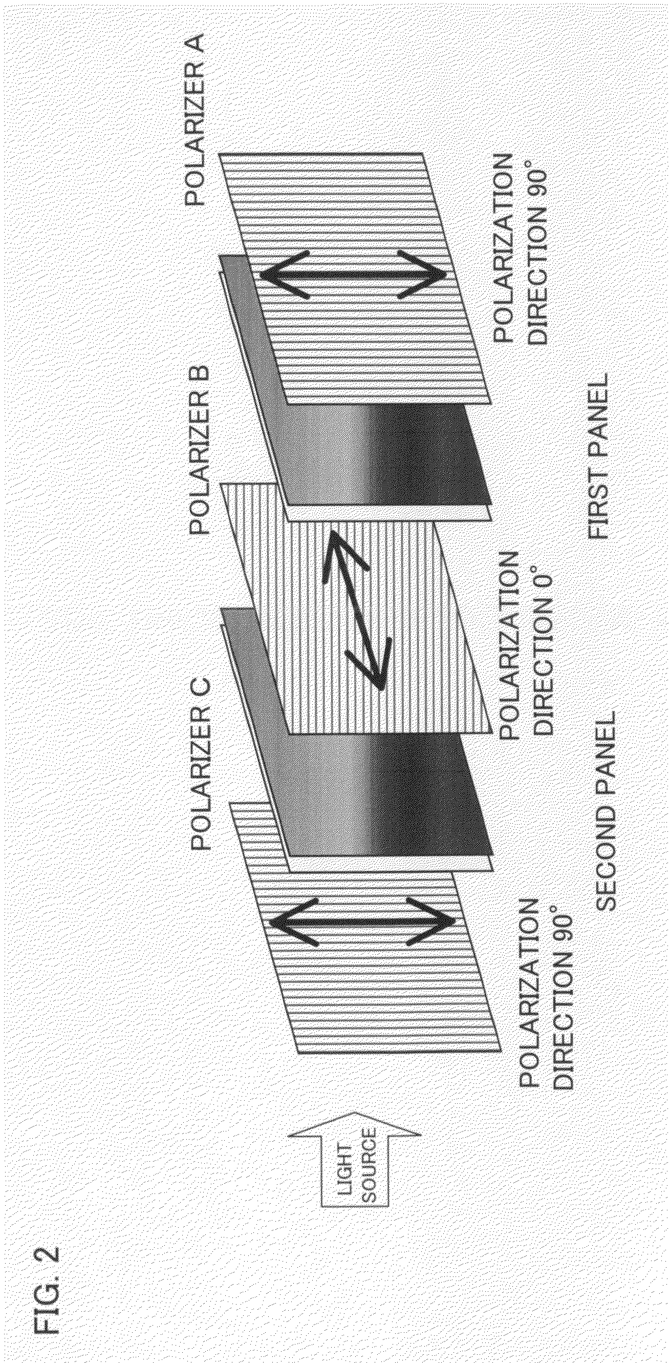
[0016]The present invention is made in view of the problem. An object of the present invention is to provide a liquid crystal display device that has high display quality in displaying not only still images but also moving images by improving both contrast and moving image performance.
[0036]With the arrangement, it is possible to provide a television receiver having high quality in displaying moving images.

Problems solved by technology

Although Patent Document 7 describes a technique for enhancing contrast, it does not focus on attaining both contrast enhancement and moving image performance enhancement.

Method used


Image

  • Liquid crystal display device, liquid crystal display method, and television receiver
  • Liquid crystal display device, liquid crystal display method, and television receiver
  • Liquid crystal display device, liquid crystal display method, and television receiver

Examples


second embodiment

[0242]The following description deals with another embodiment of the present invention. Arrangements that are not described here are the same as in the first embodiment. Accordingly, members having the same functions as the members illustrated in figures of the first embodiment have the same reference numerals as in the first embodiment, and the explanations thereof are omitted, for convenience.

[0243]In addition to the structures of the liquid crystal display device of the first embodiment, a liquid crystal display device of the present embodiment includes the following algorithms in selecting the luminance ratios Ynorm, t, A and Ynorm, t, B:

[0244](i) In calculations for the response period RT, the present embodiment checks whether the resulting values are shorter than a period of one frame or not.

[0245](ii) The present embodiment selects one that has the smallest difference between the luminance ratios Ynorm, t, A and Ynorm, t, B, when a plurality of the values for the shorter resp...

third embodiment

[0254]The following describes a television receiver adopting the liquid crystal display device of the present invention with reference to FIGS. 24 through 26.

[0255]FIG. 24 illustrates a circuit block of a liquid crystal display device 601 for the television receiver.

[0256]The liquid crystal display device 601, as illustrated in FIG. 55, includes a Y / C separation circuit 500, a video chroma circuit 501, an A / D converter 502, a liquid crystal controller 503, a liquid crystal display panel 504, a backlight drive circuit 505, a backlight 506, a microcomputer 507, and a gradation circuit 508.

[0257]The liquid crystal panel 504 includes a first liquid crystal panel and a second liquid crystal panel, but any arrangement described in the aforementioned embodiments can be applied.

[0258]With the liquid crystal display device 601 adopting the arrangement described above, first of all, an input picture signal of a television signal is inputted into the Y / C separation circuit 500, and then separa...


PUM


Abstract

A liquid crystal display device according to one embodiment of the present invention includes a display controller for outputting an image to each panel independently so that the images displayed on a first panel and a second panel are stacked with each other to form one image corresponding to an image source. The display controller includes a luminance ratio adjusting section which adjusts the gray scales of the image outputted, to each liquid crystal panel so that a display response period becomes shorter than a standard predetermined display response period in combining the gray scales, when one combined gray scale is obtained by combining the gray scales of the image outputted to each panel. This allows enhancement in contrast and moving image performance so as to realize a liquid crystal display device having high quality in displaying not only still images but also moving images.

Description

TECHNICAL FIELD[0001]The present invention relates to a liquid crystal display device, a liquid crystal display method, and a television receiver, each of which improves contrast and moving image display performance.BACKGROUND ART[0002]There are various techniques for improving contrast of a liquid crystal display device. The following Patent Documents 1 through 7 disclose such techniques.[0003]Patent Document 1 discloses a technique for improving a contrast ratio by optimizing content and a surface area ratio of a yellow pigment in pigment components of a color filter. The technique successfully resolves a problem that a contrast ratio of a liquid crystal display is reduced by use of pigment molecules, which scatter and depolarize polarized light in the color filter. According to Patent Document 1, the technique improves the contrast ratio of a liquid crystal display device from 280 to 420.[0004]Patent Document 2 discloses a technique for improving a contrast ratio by increasing tr...

Claims


Application Information

Patent Timeline
Patent Type & Authority Applications(United States)
IPC IPC(8): G09G3/36G06F3/038
CPCG02F1/133528G02F1/13471G02F2203/30G09G3/3648G09G2300/023G09G2360/02G09G2320/028G09G2320/0285G09G2320/0606G09G2320/066G09G2320/103G09G2320/0252
Inventor SAWABE, DAIICHI
Owner SHARP KK
Learn More