
Voltage controlled oscillator including inter-terminal connection and trap circuit

a voltage control and oscillator technology, applied in the direction of oscillation generators, pulse automatic control, resonance circuit tuning, etc., can solve the problem of difficulty in performing impedance matching within the frequency variable rang

Inactive Publication Date: 2009-11-12
ALPS ALPINE CO LTD
View PDF6 Cites 2 Cited by
  • Summary
  • Abstract
  • Description
  • Claims
  • Application Information

AI Technical Summary

Benefits of technology

[0009]According to an aspect of the disclosure, a voltage controlled oscillator includes: a voltage controlled oscillation circuit, an oscillation frequency thereof being controlled by a control voltage signal; PLL circuit that generates a control voltage signal to be input to the voltage controlled oscillation circuit; a multiplier circuit that multiplies an oscillation signal output from the voltage control

Problems solved by technology

When a trap circuit for removing the ½ multiplication waves (source oscillation signals) and a band-pass circuit for attenuating harmonics of 3f, 4f, are combined with

Method used


Image

  • Voltage controlled oscillator including inter-terminal connection and trap circuit
  • Voltage controlled oscillator including inter-terminal connection and trap circuit
  • Voltage controlled oscillator including inter-terminal connection and trap circuit

Examples


Embodiment Construction

[0014]An embodiment of the invention will be described hereinafter with reference to the accompanying drawings.

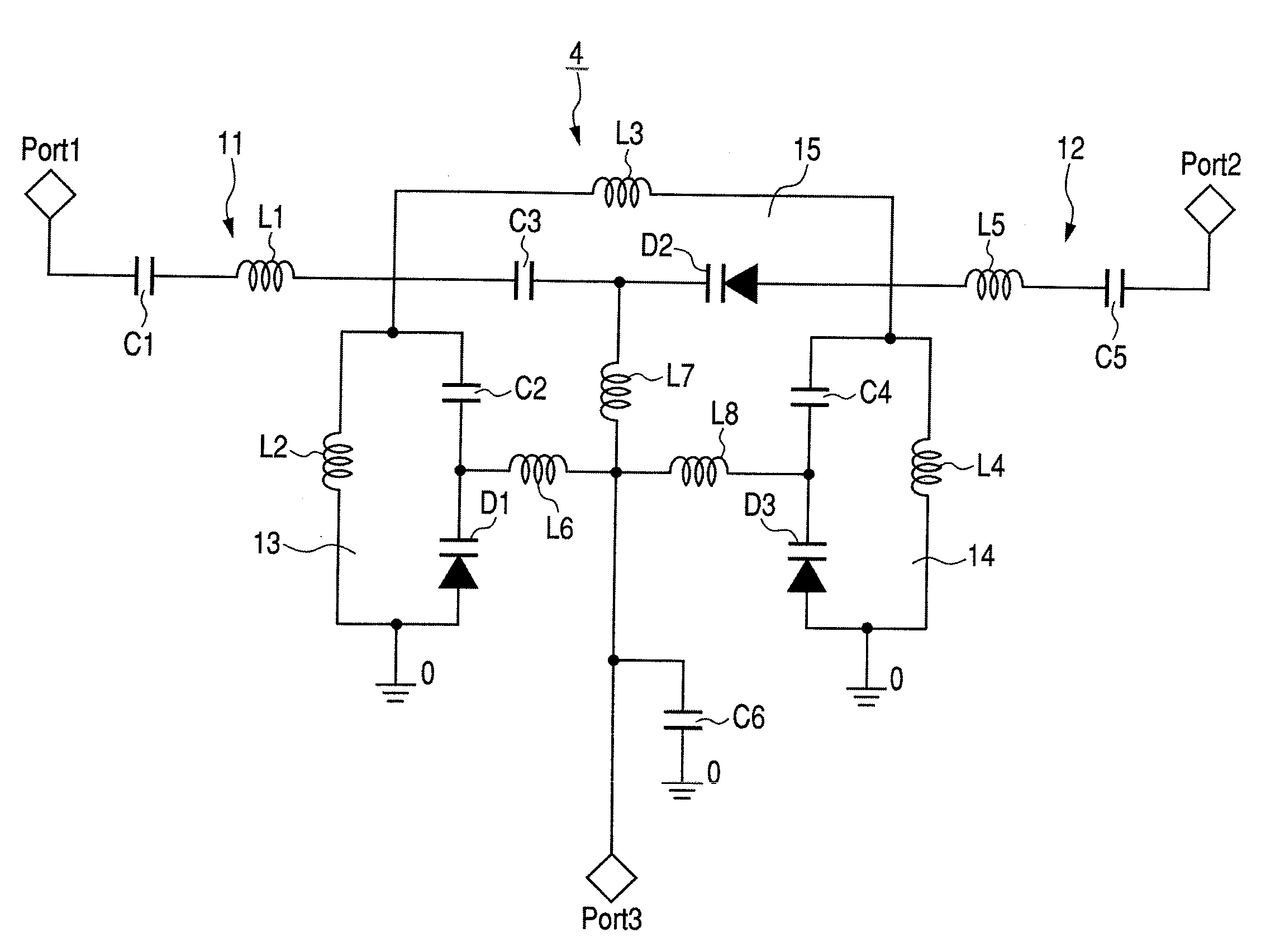
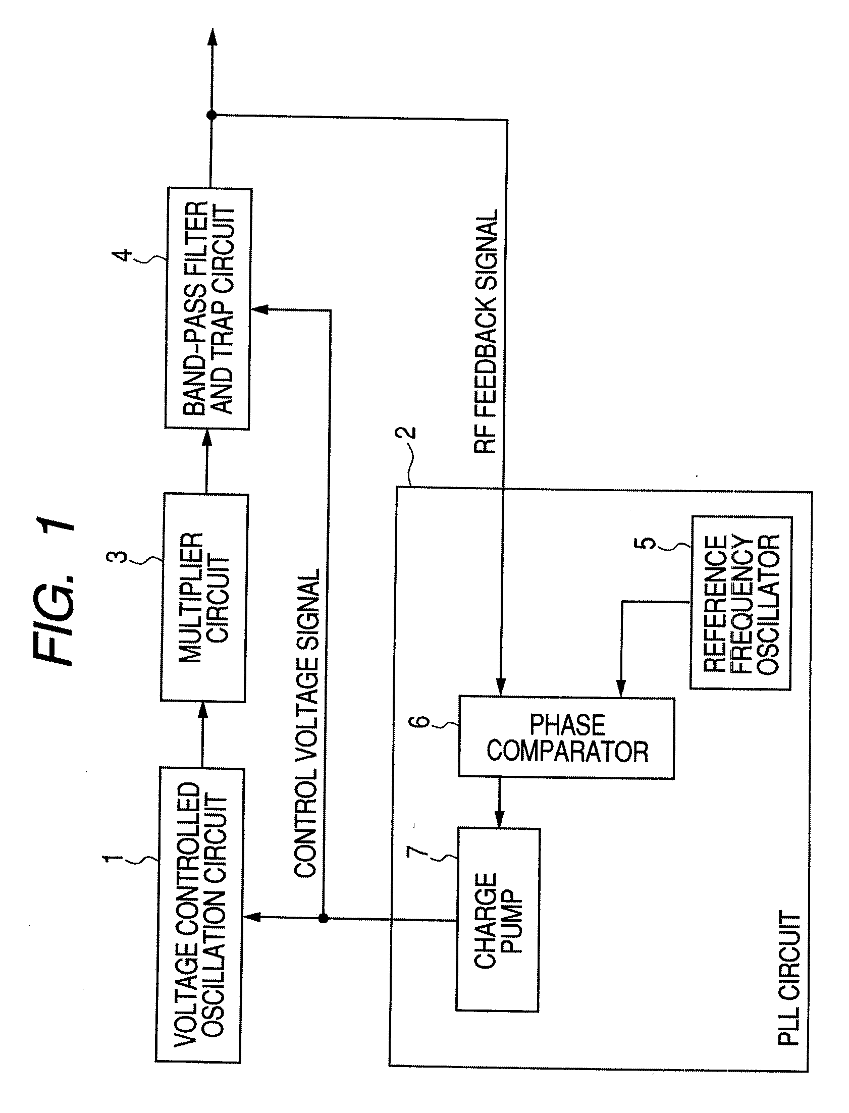
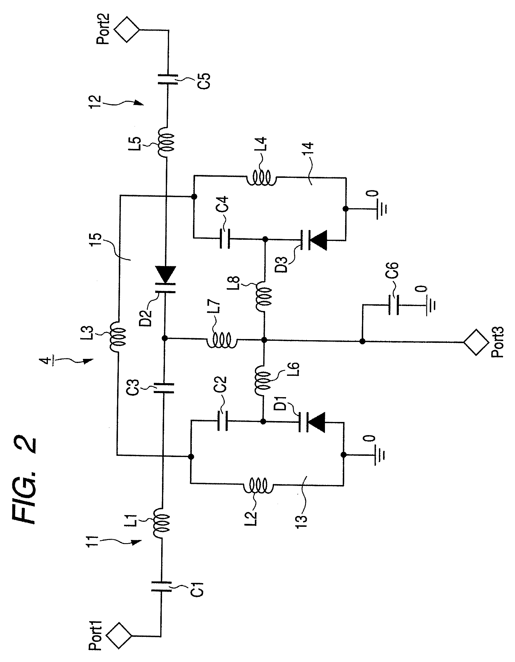
[0015]FIG. 1 is a functional block diagram illustrating a voltage controlled oscillator according to an embodiment of the invention. The voltage controlled oscillator according to the embodiment mainly includes a voltage controlled oscillation circuit 1, a PLL circuit 2 that controls an oscillation frequency of the voltage controlled oscillation circuit 1 to be a predetermined frequency, a multiplier circuit 3 that multiplies an oscillation signal output from the voltage controlled oscillation circuit 1, and a band-pass filter and trap circuit 4, to which signals (multiplication output signal and source oscillation signal) output from the multiplier circuit 3 are input, and which varies a trap frequency and a pass band in synchronization with a control voltage signal.

[0016]The voltage controlled oscillation circuit 1 is configured to control a frequency of the oscillation s...


PUM


Abstract

A voltage controlled oscillator includes: a voltage controlled oscillation circuit, an oscillation frequency thereof being controlled by a control voltage signal; a PLL circuit that generates a control voltage signal to be input to the voltage controlled oscillation circuit; a multiplier circuit that multiplies an oscillation signal output from the voltage controlled oscillation circuit; and a band-pass filter and trap circuit that sets a pass band for passing a signal with a predetermined multiplication number of multiplication signals output from the multiplier circuit and a trap frequency equal to the frequency of the oscillation signal input to the multiplier circuit, and varies the pass band and the trap frequency in synchronization with the control voltage signal.

Description

CROSS REFERENCE TO RELATED APPLICATIONS [0001]The present application claims priority to Japanese Patent Application No. 2008-124546 filed in the Japanese Patent Office on May 12, 2008, the entire contents of which being incorporated herein by reference.BACKGROUND[0002]1. Technical Field[0003]The present invention relates a voltage controlled oscillator to obtain an oscillation signal with a desired frequency by multiplying an oscillation signal.[0004]2. Related Art[0005]In the field of mobile radio communication, an oscillation signal generated by a local oscillator is input to a mixer to perform frequency conversion. Recently, a local oscillator with a high frequency and a wide variable width is being demanded. In the related art, a voltage controlled oscillator has been known, in which an output of the voltage controlled oscillator is multiplied to widen a variable width of the voltage controlled oscillator, and then a multiplication signal with a desired frequency is taken out t...

Claims


Application Information

Patent Timeline
IPC IPC(8): H03L7/085
CPCH03B19/00H03J3/185H03L2207/10H03L7/099H03J3/26
Inventor NAKATSUKA, KENJI
Owner ALPS ALPINE CO LTD
Learn More