
Inductive Rotary Joint

a rotary joint and inductive technology, applied in the direction of ratio control, mechanical power/torque control, special data processing applications, etc., can solve the problems of requiring information from a sensor to be transmitted from the output side to the input side, and more complex filter structures may be obtained

Active Publication Date: 2009-11-05
SCHLEIFRING & APPBAU
View PDF11 Cites 16 Cited by
  • Summary
  • Abstract
  • Description
  • Claims
  • Application Information

AI Technical Summary

Benefits of technology

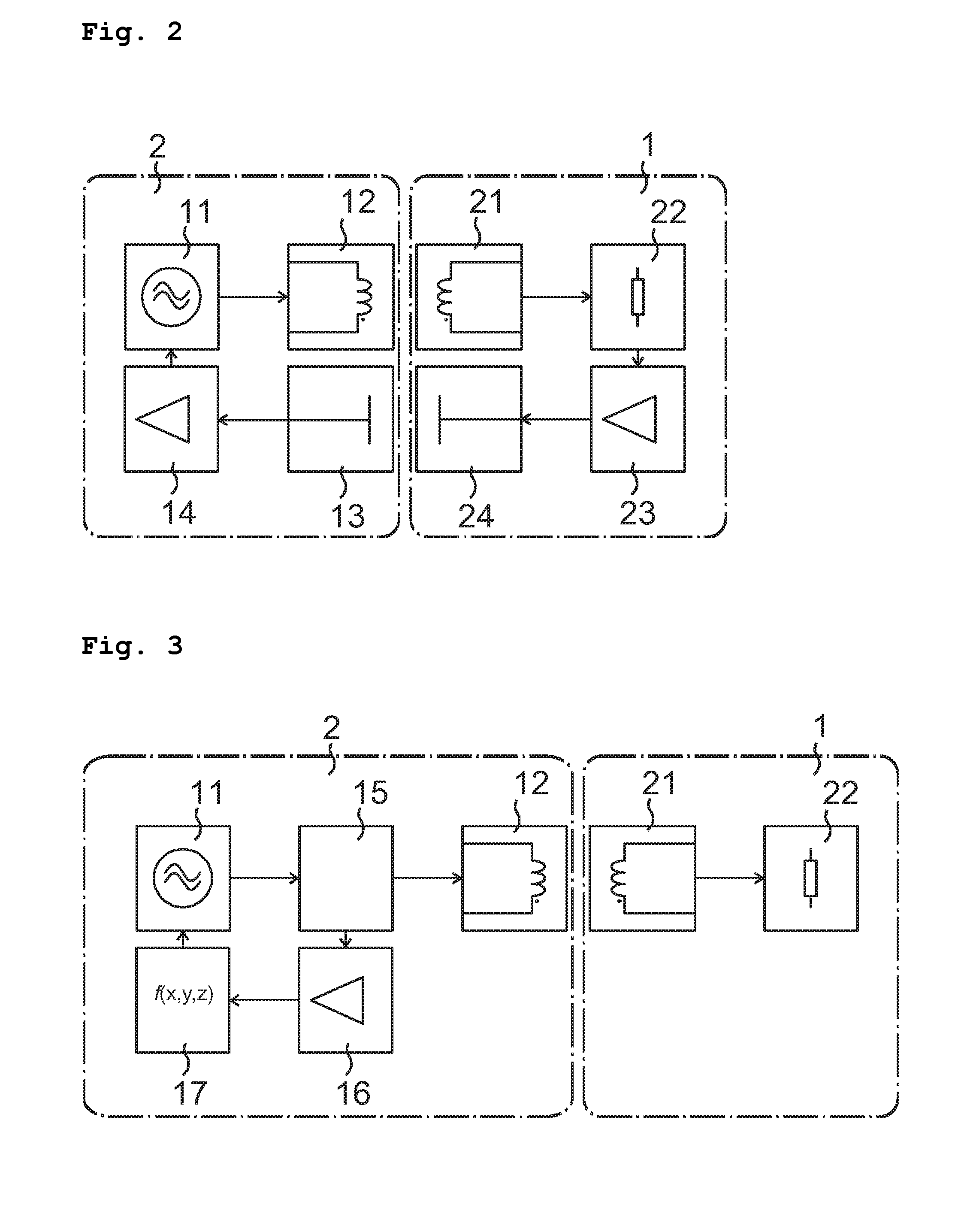
[0023]For feeding the load 22, the primary side 12 of the power transmitter is magnetically coupled with the secondary side 21 of the power transmitter. A measuring amplifier 23 determines particular measurement parameters, which characterize the load 22 or an operating state of the load. A measurement parameter of this kind may be, for example, a voltage applied to the load, or a current flowing through the load. Typically, a load 22 is supplied with direct current. For this reason, a rectifier (not shown) with optional smoothing and optional control circuitry is provided between the load 22 and the secondary side 21 of the power transmitter. In this case, the measurement parameter would be a direct current voltage on the load 22 or a direct current through the load 22.

Problems solved by technology

Of course, more complex filter structures also may be obtained.
With circuits of this kind, it is a problem that a measurement means is always needed on the output side of the rotary joint.
With rotary joints, however, there is the problem that information from a sensor must be transmitted from the output side to the input side, i.e., between two units that are rotatable relative to each other.
However, often no mechanical construction space is available for a capacitive coupling element of this kind, or else a coupling element of this kind is needed for data transmission for other data such as measurement data, for example, and therefore cannot be used for regulating purposes.
The problems described above increase with increase of size of the rotary joint.
This leads to a substantially larger stray inductance, which fluctuates substantially more strongly.

Method used


Image

  • Inductive Rotary Joint
  • Inductive Rotary Joint
  • Inductive Rotary Joint

Examples


Embodiment Construction

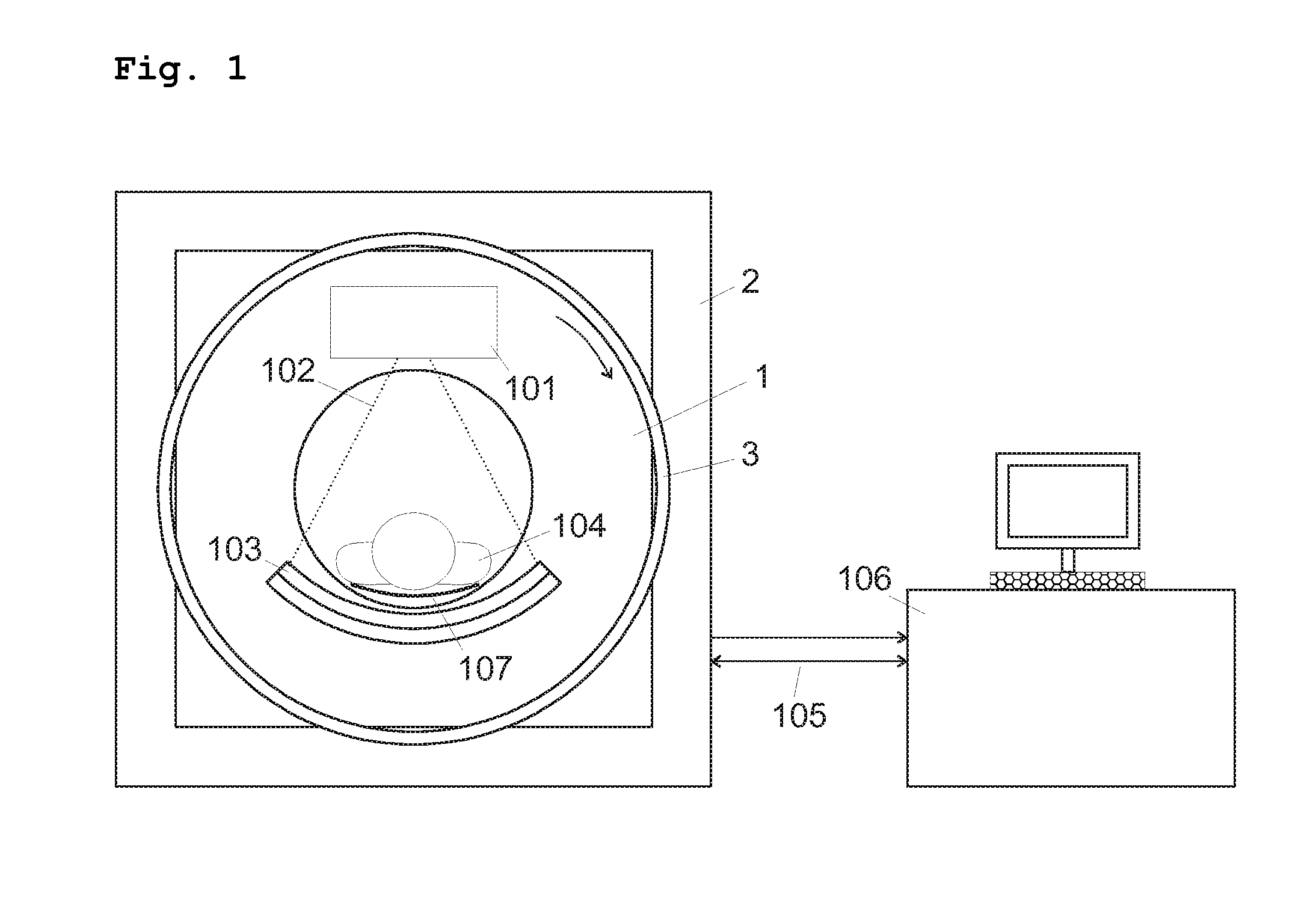
[0021]FIG. 1 shows an embodiment of a computer tomograph (CT) scanner comprising two mechanical main parts. A stationary part 2 serves as a base and support for the entire instrument, within which a rotating part 1 revolves. A patient 104 is positioned on a berth 107 in an opening of the rotating part. An X-ray tube 101 and an oppositely positioned detector 103 are provided for scanning the patient by means of X-rays 102. The X-ray tube 101 and the detector 103 are disposed to be rotatable on the rotating part 1. A rotary joint 3 serves to provide an electrical connection between the rotating part 1 and the stationary part 2 of the CT machine. In this, high electrical power for feeding the X-ray tube 101 is transmitted in a direction towards the rotating part 1, and raw data of an image obtained by the detector 103 are simultaneously transmitted in an opposite direction. A communication of control information in both directions is provided in parallel with this. An evaluation and co...


PUM


Abstract

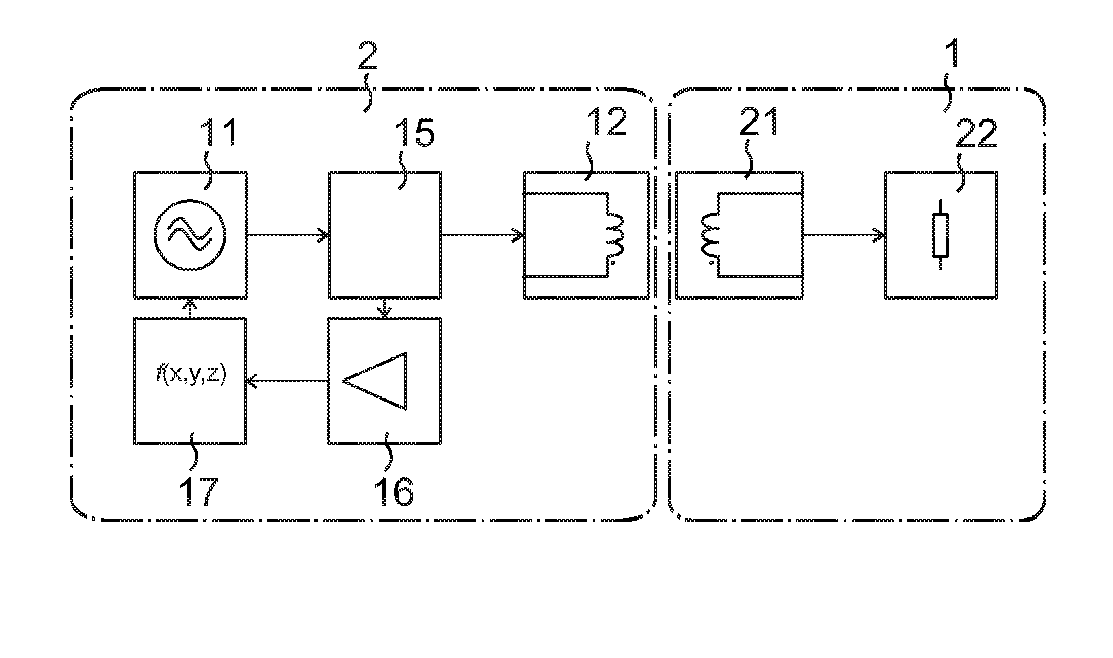
An inductive rotary joint for non-contact transmission of electrical energy between a stationary part and a rotating part of the rotary joint comprises a power generator for generating an alternating voltage or an alternating current, which feeds a load by means of a rotatable power transmitter. An electrical parameter on the primary side of the power transmitter is determined with a measurement means, and from this, the condition of another electrical parameter at the load is approximated by means of a functional unit. Regulation of the power generator is effected with this approximated value.

Description

PRIORITY CLAIM[0001]The present application is a continuation of pending International Patent Application No. PCT / EP2007 / 009631 filed on Nov. 7, 2007, which designates the United States and claims priority to German Patent Application No. 102006052685.6 filed on Nov. 7, 2006 (now abandoned).BACKGROUND OF THE INVENTION[0002]1. Field of the Invention[0003]The invention relates to an inductive rotary joint for transmitting electrical power between two units that are rotatable relative to each other, in particular for use in computer tomographs.[0004]2. Description of the Related Art[0005]Non-contacting inductive rotary joints are an advantageous substitute for the known mechanical slip-rings for transmission of electrical energy. In inductive transmission technology a coupling between rotatable units is effected with magnetic fields without contact. This has an advantage over mechanical slip-rings in that torque, wear, and thus, also an outlay of servicing are minimized. Furthermore, t...

Claims


Application Information

Patent Timeline
IPC IPC(8): G06G7/48G06F19/00G06F17/50
CPCA61B6/03A61B6/56H02P9/10H01F2038/143H02J5/005H01F38/18H02J50/12H02J2310/23
Inventor KRUMME, NILSLOHR, GEORGWEITHMANN, HERBERTBLEY, MICHAEL
Owner SCHLEIFRING & APPBAU
Learn More