
Computer cooling apparatus

Inactive Publication Date: 2009-11-05
THERMALTAKE
View PDF8 Cites 16 Cited by
  • Summary
  • Abstract
  • Description
  • Claims
  • Application Information

AI Technical Summary

Benefits of technology

[0005]Therefore, it is a primary objective of the present invention to provide a computer cooling apparatus having a heat absorbing unit for absorbing a related heat source in a computer and a cooling unit for exchanging heat to provide a quick way of dispersing the heat source and a better heat dissipating effect.

Problems solved by technology

Thus, the heat dissipation efficiency is low and the heat dissipation effect is poor.

Method used


Image

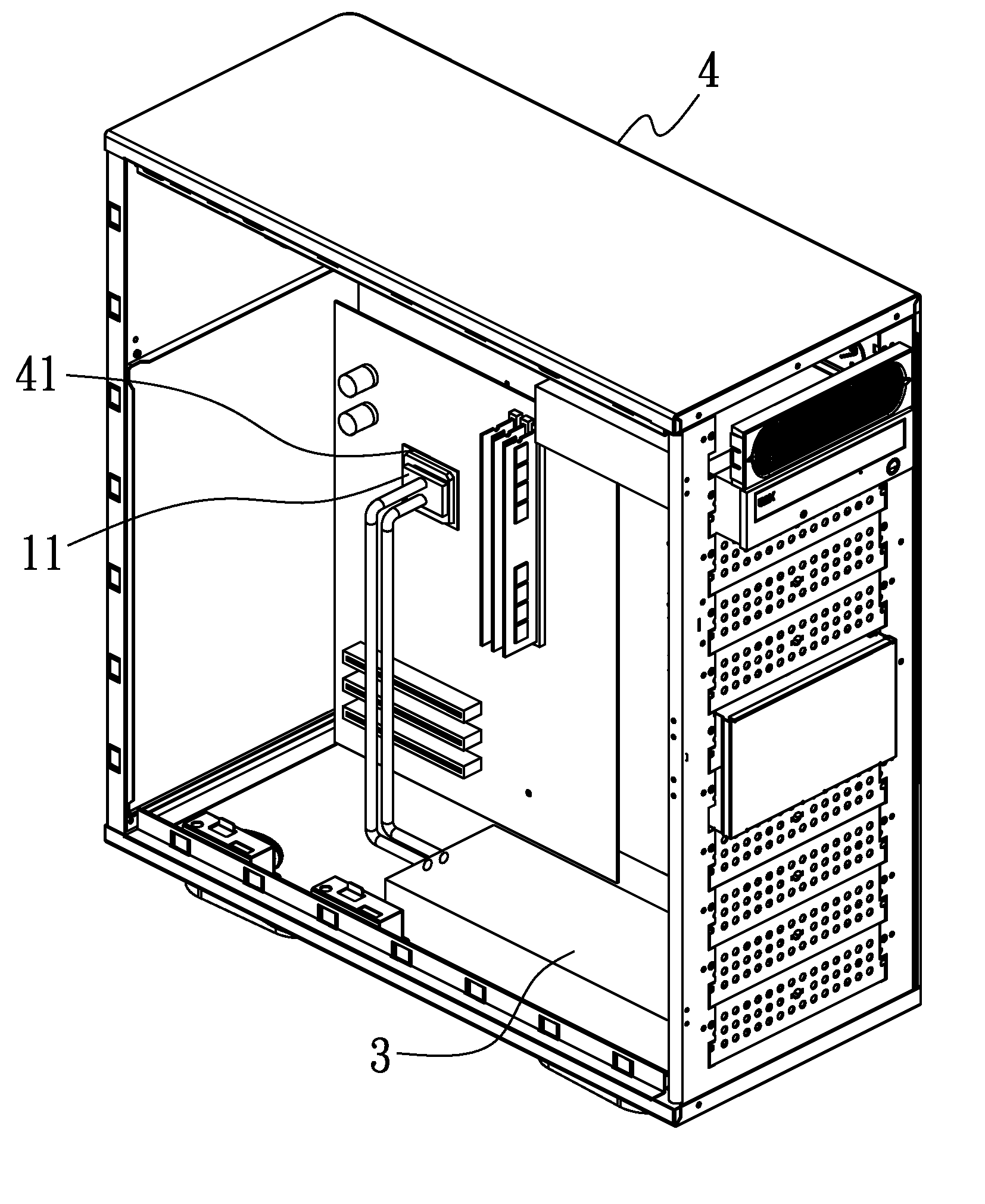
  • Computer cooling apparatus
  • Computer cooling apparatus
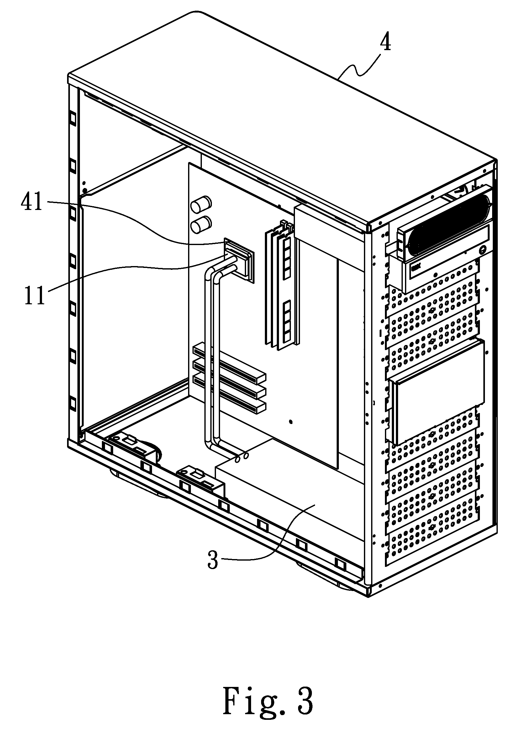
  • Computer cooling apparatus

Examples


Embodiment Construction

[0012]The above and other objects, features and advantages of the present invention will become apparent from the following detailed description taken with the accompanying drawing.

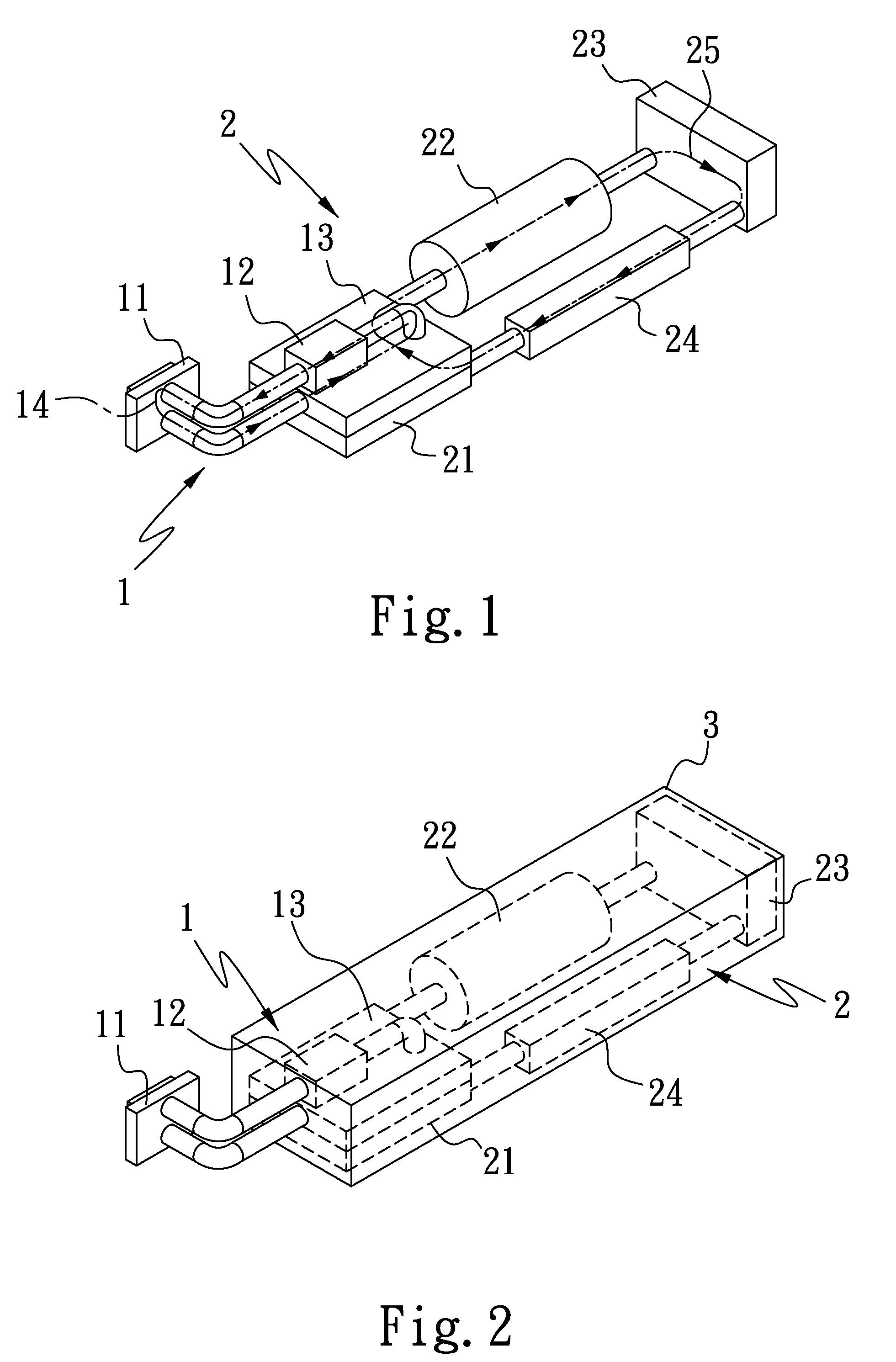
[0013]Referring to FIG. 1 for a perspective view of a first preferred embodiment of the present invention, an improved computer cooling apparatus of the invention comprises a heat absorbing unit 1 and a cooling unit 2.

[0014]The heat absorbing unit 1 includes at least one water cooling block 11, a pump 12 connected to the water cooling block 11, and a heat exchanger 13 connected to the pump 12, and a first working fluid 14 flows through the water cooling block 11, the pump 12 and the heat exchanger 13, wherein the first working fluid 14 is water.

[0015]The cooling unit 2 includes an evaporator 21 attached to the heat exchanger13, a compressor 22 connected to the evaporator 21, a condenser 23 connected to the compressor 22, and an expansion valve 24 connected to the condenser 23, and a second working fluid 2...


PUM


Abstract

An improved computer cooling apparatus includes: a heat absorbing unit, having at least one water cooling block, a pump connected to the water cooling block, and a heat exchanger connected to the pump, and a first working fluid flows through the water cooling block, the pump and the heat exchanger; and a cooling unit, having an evaporator attached onto the heat exchanger, a compressor connected to the evaporator, a condenser connected to the compressor, and an expansion valve connected to the condenser, and a second working fluid flows through the evaporator, the compressor, the condenser and the expansion valve. The heat absorbing unit absorbs a related heat source in a computer, and a cooling unit dissipates the heat to provide a quick way of dispersing the heat source and a better heat dissipating effect.

Description

FIELD OF THE INVENTION[0001]The present invention relates to an improved computer cooling apparatus, and more particularly to a computer cooling apparatus having a heat absorbing unit for absorbing a related heat source in a computer and a cooling unit for exchanging heat to provide a quick way of dispersing the heat source and a better heat dissipating effect.BACKGROUND OF THE INVENTION[0002]In general, a conventional water cooling assembly of a heat dissipating apparatus includes a base, an upper casing having a containing space and covered onto the base, and input and output pipes installed on one side of the upper casing and interconnected with the containing space, such that the base can be attached onto a central processing unit (CPU) on a motherboard, and a working fluid is allowed to flow from the input pipe into the containing space for absorbing a heat source absorbed in the base. After the heat is absorbed, the heat source in the containing space absorbed by the working f...

Claims


Application Information

Patent Timeline
IPC IPC(8): F25B1/00
CPCG06F1/20
Inventor LIN, PEI-HSI
Owner THERMALTAKE
Learn More