Stability control system with body-force-disturbance heading correction
- Summary
- Abstract
- Description
- Claims
- Application Information
AI Technical Summary
Benefits of technology
Problems solved by technology
Method used
Image
Examples
Embodiment Construction
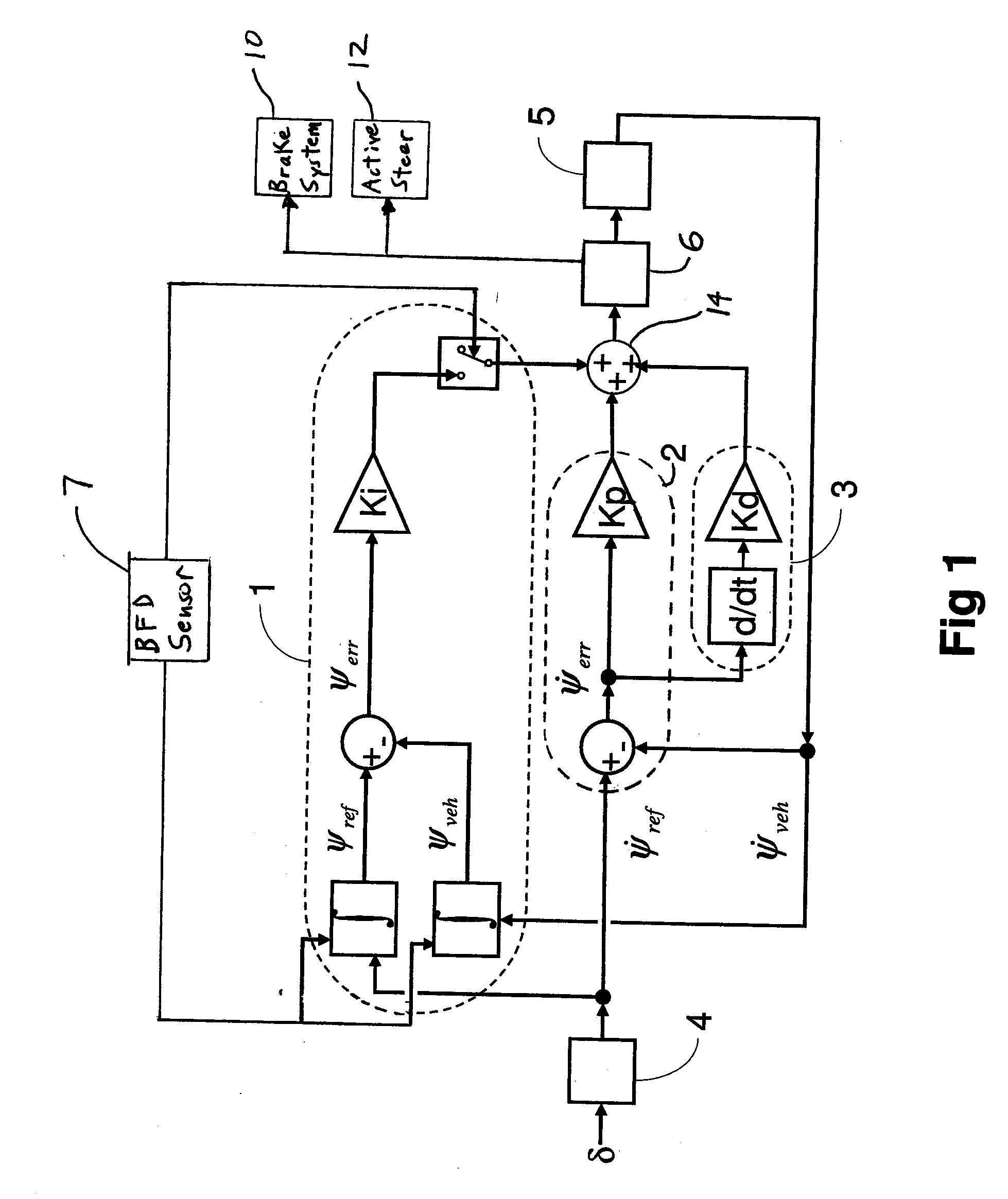
[0024]FIG. 1 illustrates a yaw stability control system and method of operation that is responsive to a yaw rate error, here shown as having a yaw rate proportional module 2 and a yaw rate derivative module 3. The yaw rate error signal {dot over (ψ)}err is determined or calculated as the difference between a reference or target yaw rate signal {dot over (ψ)}ref, provided from a yaw rate reference model 4 to which the steering wheel angle δ is input, and a sensed vehicle yaw rate signal {dot over (ψ)}veh, provided by vehicle dynamic sensors 5. This yaw rate error {dot over (ψ)}err is subjected to the yaw rate proportional 2 and yaw rate derivative 3 modules of the controller algorithm. Scaling or gain factors Kp and Kd are applied to the respective signals as required, then the signals are combined at an arithmetic node 14 to create an input to a yaw control module 6. This input may be seen as carrying a yaw torque request. In response to the signals received from the yaw rate propor...
PUM
 Abstract
Description
Claims
Application Information
 - R&D
- Intellectual Property
- Life Sciences
- Materials
- Tech Scout
- Unparalleled Data Quality
- Higher Quality Content
- 60% Fewer Hallucinations
Browse by: Latest US Patents, China's latest patents, Technical Efficacy Thesaurus, Application Domain, Technology Topic, Popular Technical Reports.
© 2025 PatSnap. All rights reserved.Legal|Privacy policy|Modern Slavery Act Transparency Statement|Sitemap|About US| Contact US: help@patsnap.com


