
Image pickup lens and image pickup apparatus

a technology of image pickup and image, which is applied in the direction of optics, instruments, optics, etc., can solve the problems of reducing the manufacturing sensitivity of image pickup lenses. , to achieve the effect of reducing the total optical length, improving optical performance, and reducing the manufacturing sensitivity of image pickup lenses

Inactive Publication Date: 2009-10-29
SONY CORP
View PDF2 Cites 11 Cited by
  • Summary
  • Abstract
  • Description
  • Claims
  • Application Information

AI Technical Summary

Benefits of technology

[0009]On the other hand, the image pickup lens disclosed in Japanese Unexamined Patent Application Publication No. 2005-292559 includes four lens elements and has high aberration correctability. Instead, the image pickup lens has a long total optical length, preventing size reduction. In addition, the image pickup lens has an aperture stop at the front end of its optical system, i.e., on the object side with respect to a first lens element. This increases manufacturing sensitivity, resulting in large changes in aberrations due to, for example, axial misalignment between lens elements, and therefore may cause a reduction in optical performance.
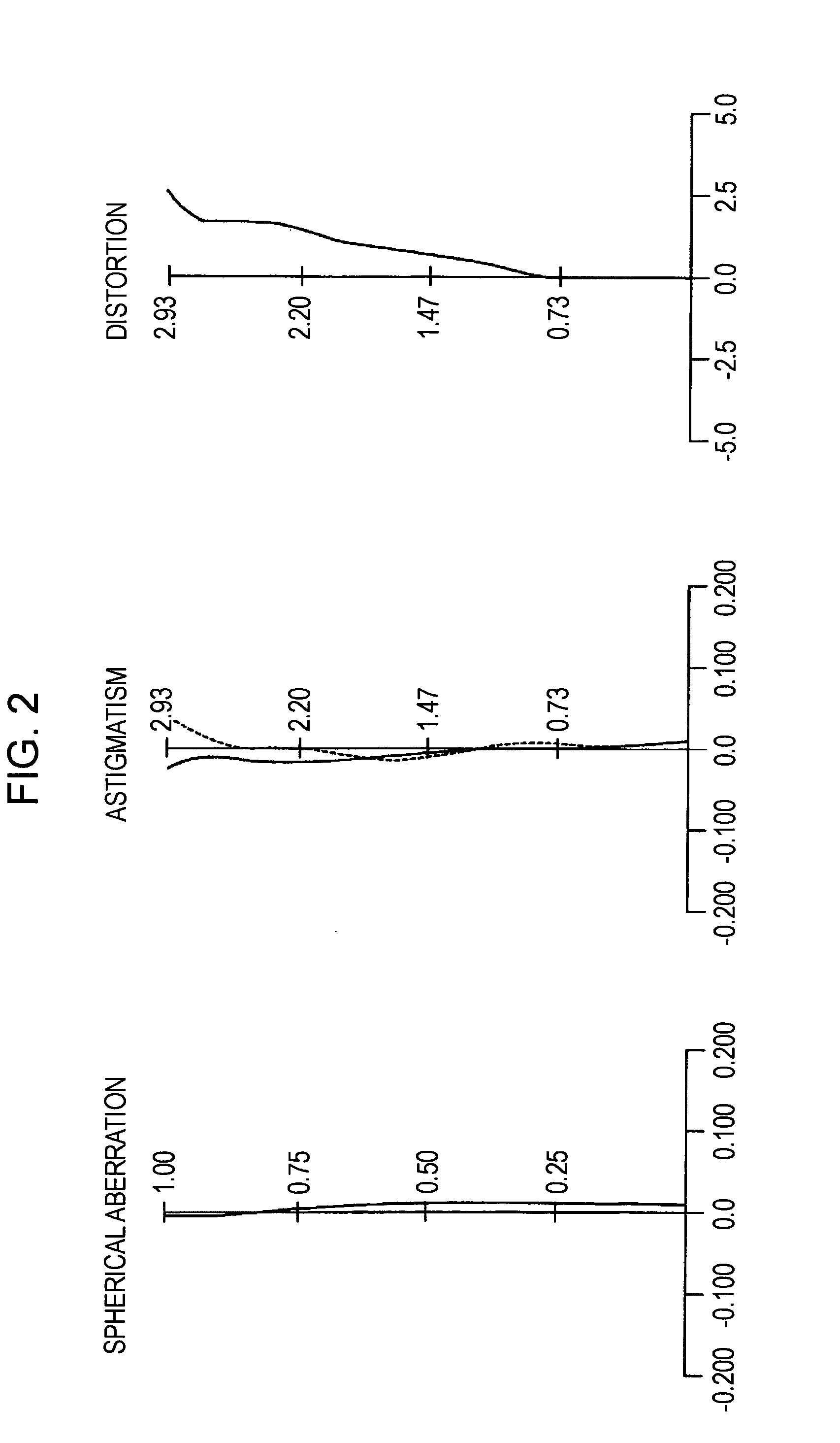
[0022]In addition, in the image pickup apparatus satisfying the above conditional expressions, aberrations occurring with increase in the number of pixels included in the image pickup device can be corrected well, and therefore optical performance can be improved.

Problems solved by technology

However, the image pickup lens including such a reduced number of lens elements is difficult to be used with a recent image pickup device including a large number of pixels.
In other words, since the image pickup lens includes only a small number of lens elements, it is difficult to realize desirable correction of aberrations occurring with the increasing number of pixels included in the image pickup device.
In particular, it is difficult to accommodate high resolutions and to correct chromatic aberration.
This increases manufacturing sensitivity, resulting in large changes in aberrations due to, for example, axial misalignment between lens elements, and therefore may cause a reduction in optical performance.

Method used


Image

  • Image pickup lens and image pickup apparatus
  • Image pickup lens and image pickup apparatus
  • Image pickup lens and image pickup apparatus

Examples


Embodiment Construction

[0032]Embodiments of the image pickup lens and the image pickup apparatus according to the present invention will now be described.

[0033]A general embodiment of the image pickup lens according to the present invention will first be described.

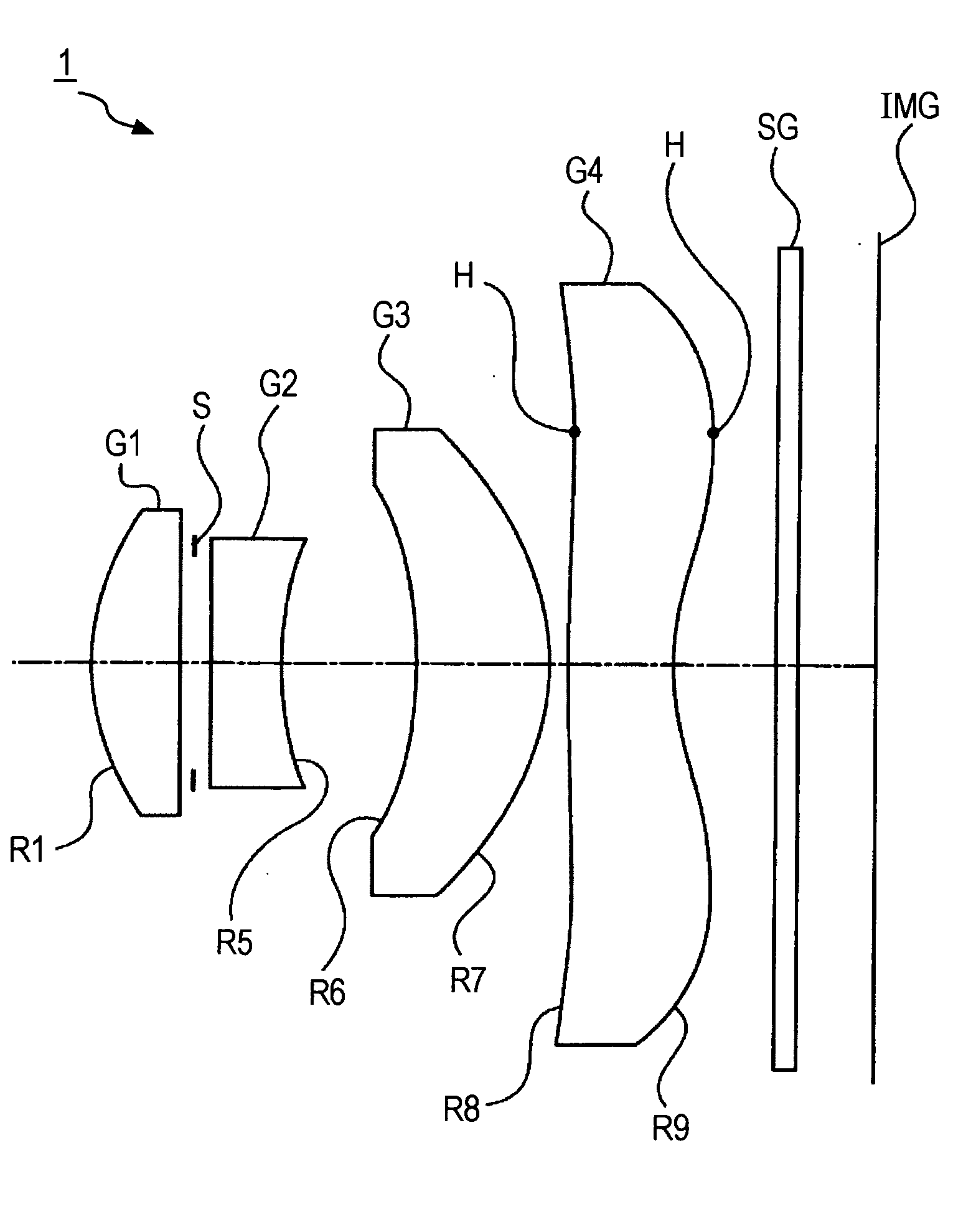
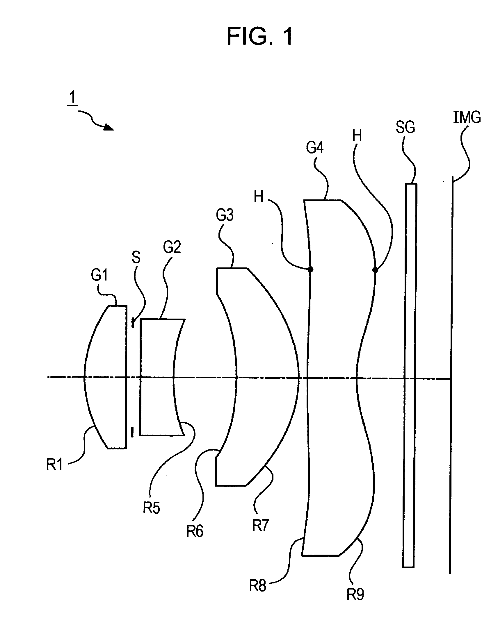
[0034]An image pickup lens according to the general embodiment includes, in order from an object side, a first lens element having a positive refractive power and a convex surface facing the object side, an aperture stop adjusting the amount of light, a second lens element having a negative refractive power, a third lens element having a positive refractive power and a concave surface facing the object side, and a fourth lens element having a negative refractive power.

[0035]As described above, in the image pickup lens according to the general embodiment, the aperture stop is disposed between the first lens element and the second lens element. Therefore, changes in aberrations due to axial misalignment between the lens elements are smaller than i...


PUM


Abstract

An image pickup lens includes, in order from an object side, a first lens element having a positive refractive power and a convex surface facing the object side, an aperture stop adjusting the amount of light, a second lens element having a negative refractive power, a third lens element having a positive refractive power and a concave surface facing the object side, and a fourth lens element having a negative refractive power. In the image pickup lens, the following conditional expressions are satisfied,0.6<|f2 / f|<1.80≦f2 / R4<1.7where f denotes a focal length of an entire lens system, f2 denotes a focal length of the second lens element, and R4 denotes a curvature radius of an object-side surface of the second lens element.

Description

BACKGROUND OF THE INVENTION[0001]1. Field of the Invention[0002]The present invention relates to image pickup lenses and image pickup apparatuses, and more specifically to a technical field of an image pickup lens having a small size and improved optical performance, and an image pickup apparatus including the image pickup lens.[0003]2. Description of the Related Art[0004]Many of common image pickup apparatuses, such as camera-equipped mobile phones and digital still cameras, include charge-coupled devices (CCDs) and complementary metal-oxide semiconductors (CMOSs), for example, functioning as solid-state image pickup devices.[0005]In recent years, there has been an increasing demand for size reduction in such image pickup apparatuses. Accordingly, image pickup lenses to be included in these apparatuses are desired to have short total optical lengths. In response to this trend, Japanese Unexamined Patent Application Publication No. 2007-155868 discloses an exemplary image pickup app...

Claims


Application Information

Patent Timeline
Patent Type & Authority Applications(United States)
IPC IPC(8): G02B9/34
CPCG02B9/34G02B13/18G02B13/004
Inventor ONODA, YOSHITOMO
Owner SONY CORP
Learn More