
Fluid control system

a control system and fluid technology, applied in fluid pressure control, diaphragm valves, instruments, etc., can solve the problems of difficult use for applications controlling the flow rate over a broad flow rate range, complicated work, and time-consuming, etc., to achieve easy installation work, shorten work time, and reduce the space of the installation location

Inactive Publication Date: 2009-10-29
ASAHI YUKIZAI KOGYO CO LTD
View PDF18 Cites 16 Cited by
  • Summary
  • Abstract
  • Description
  • Claims
  • Application Information

AI Technical Summary

Benefits of technology

[0007]The present invention was made in consideration of the above problems in the prior art and has as its object the provision of a fluid control system facilitating installation, piping, and wiring in a semiconductor production facility etc., enabling control of the flow rate without problem even when a pulsating fluid flows, and enabling stable, precision control of the flow rate over a broad flow rate range.

Problems solved by technology

However, said conventional pure water flow rate control system 301 balanced with the outlet pressure of the pure water at the flow rate adjusting valve 302 so as to control the flow rate of the pure water output from the flow rate adjusting valve 302 to a constant value, so was not suited to fine control of the flow rate.
The flow rate range was also not that wide, so there was the problem that this was hard to use for applications controlling the flow rate over a broad flow rate range.
The work was complicated and required time.
Further, the piping and wiring were troublesome and mistakes were liable to be made.
Further, said conventional flow rate control module 306 had the problem that when the fluid flowing into the fluid control system was a pulsating flow with a short period of fluctuation of pressure, the control valve 308 would operate to try to control the flow rate for the pulsating fluid, but there was the problem that hunting would occurred and flow rate control would no longer be possible and, if continued as is, the driver 311 or the control valve 308 would end up breaking down.
Further, the flow rate range for control of the flow rate was not that wide, so there was the problem that this was hard to use for applications controlling the flow rate over a broad flow rate range.

Method used


Image

  • Fluid control system
  • Fluid control system
  • Fluid control system

Examples


first embodiment

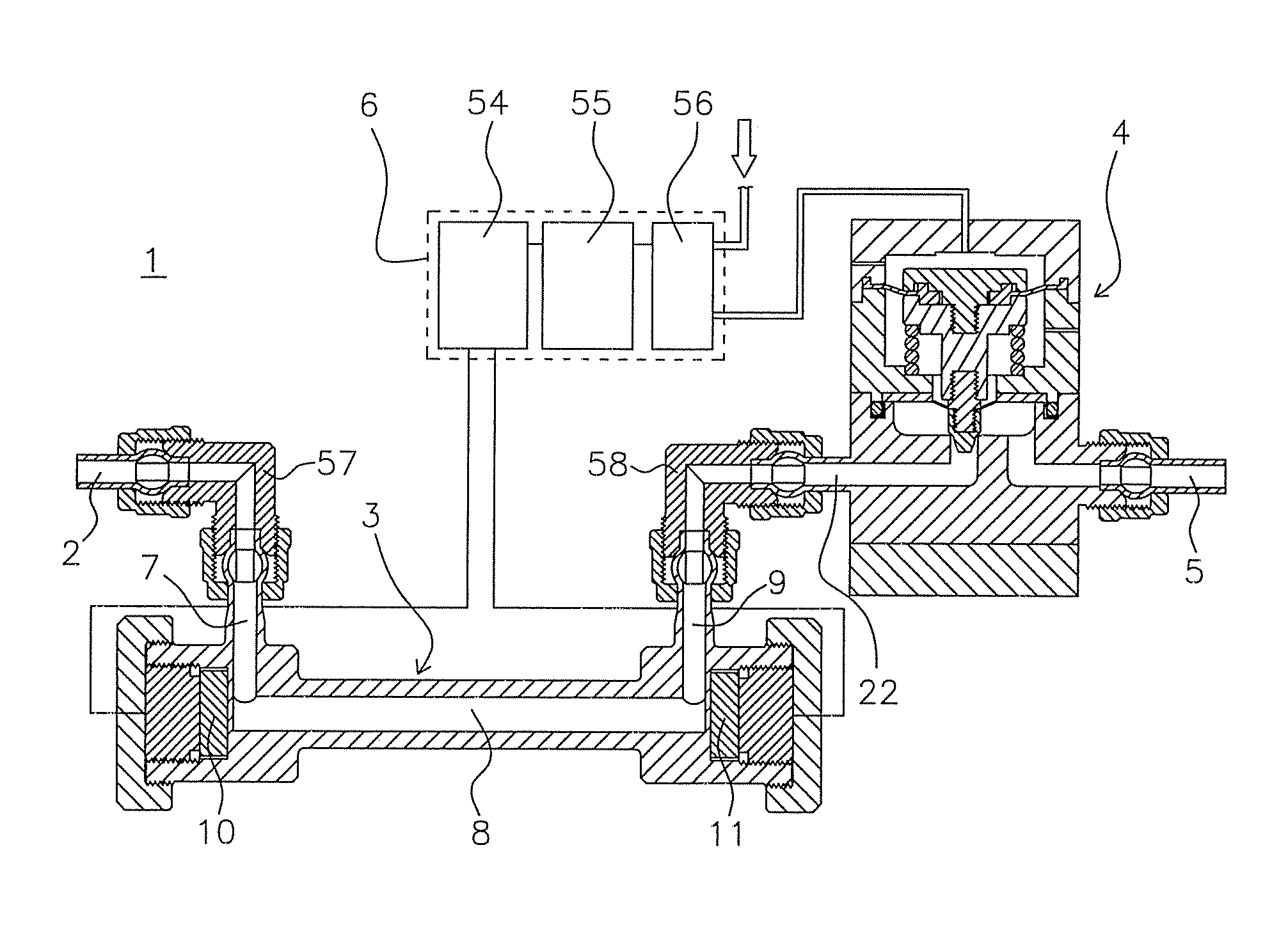
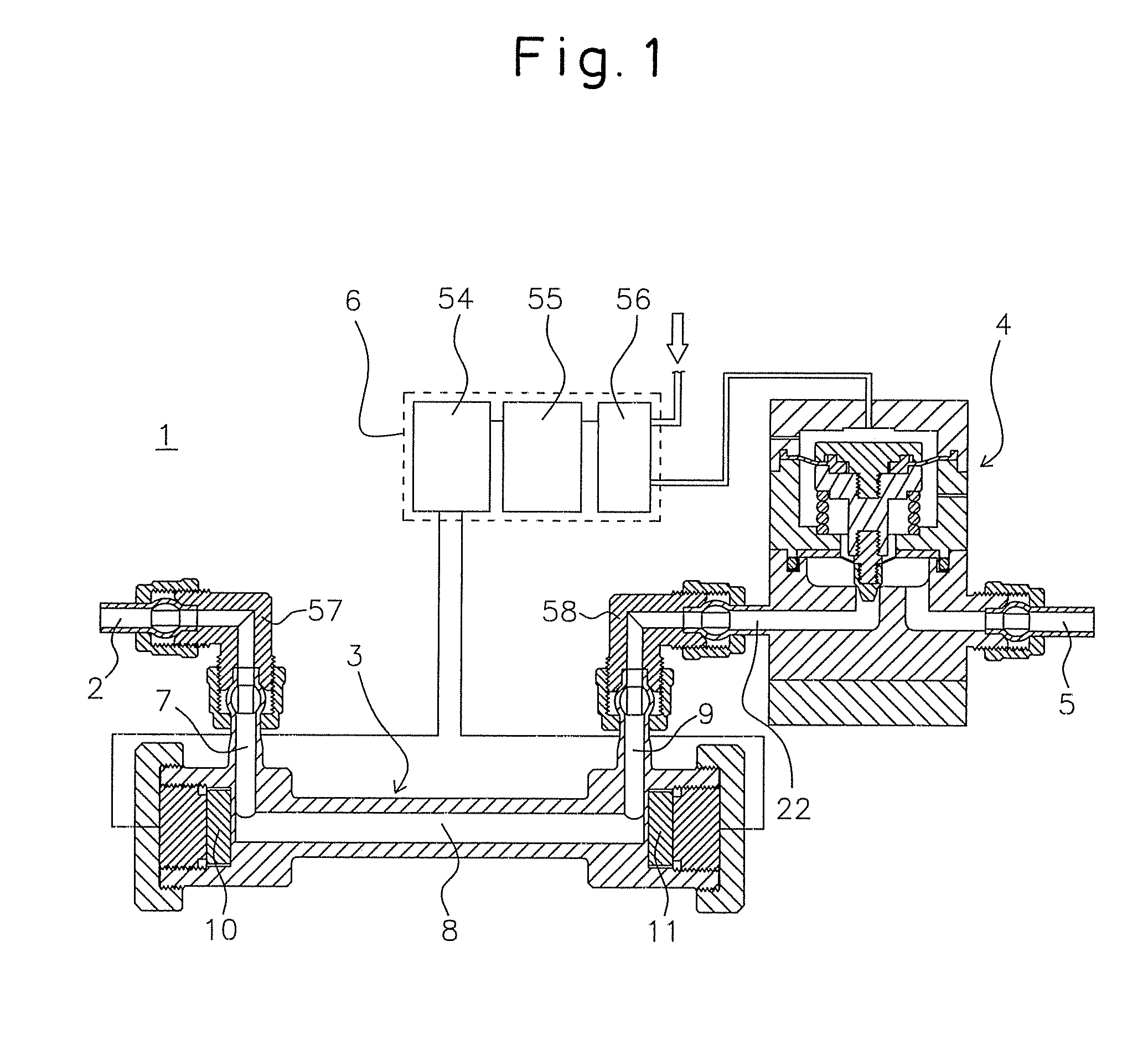
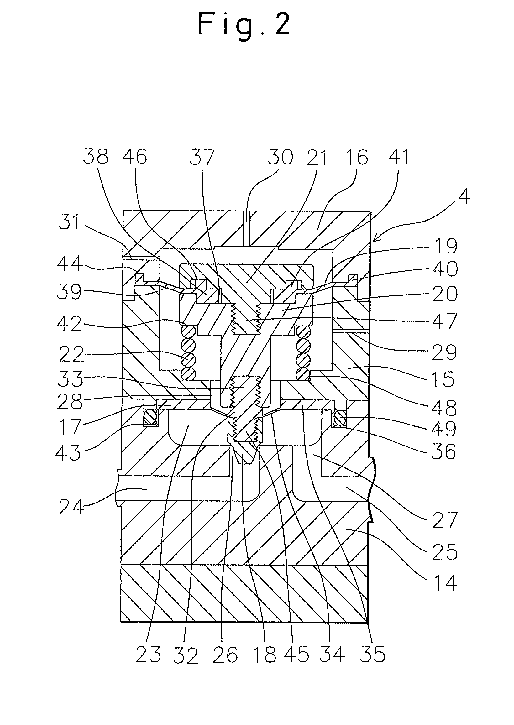
[0066]Below, a fluid control system of a first embodiment of the present invention will be explained with reference to FIG. 1 and FIG. 2.

[0067]1 is a fluid control system installed in a semiconductor production facility performing an etching process in the production of semiconductors. The fluid control system 1 is formed from a fluid inflow port 2, flow rate measuring device 3, fluid control valve 4, fluid outflow port 5, and control part 6. These are configured as follows:

[0068]2 is a PFA fluid inflow port. The fluid inflow port 2 is communicated with an inlet passage 7 of the later-mentioned flow rate measuring device 3.

[0069]3 is a flow rate measuring device for measuring the flow rate of a fluid. The flow rate measuring device 3 has an inlet passage 7, a straight passage 8 provided vertical from the inlet passage 7, and an outlet passage 9 provided vertical from the straight passage 8 and provided in parallel to the inlet passage 7 in the same direction. Ultrasonic oscillators ...

second embodiment

[0092]Next, a fluid control system of a second embodiment of the present invention will be explained with reference to FIG. 3 and FIG. 4.

[0093]As shown in FIG. 3, a fluid control system 59 is formed from a fluid inflow port 60, shutoff valve 61, flow rate measuring device 62, fluid control valve 63, fluid outflow port 64, and control part 65. These parts are configured as follows:

[0094]As shown in FIG. 4, the shutoff valve 61 is formed from a main body 66, a drive unit 67, a piston 68, a diaphragm holder 69, and a valve element 70.

[0095]66 is a PTFE main body. It has a valve chamber 71 at the center of the top end in the axial direction and an inlet passage 72 and outlet passage 73 communicating with the valve chamber 71. The inlet passage 72 communicates with the fluid inflow port 60, while the outlet passage 73 communicates with the flow rate measuring device 62. Further, at the outer side of the valve chamber 71 at the top face of the main body 66, a ring-shaped groove 74 is prov...

third embodiment

[0105]Next, a fluid control system of a third embodiment of the present invention will be explained with reference to FIG. 5 and FIG. 6.

[0106]As shown in FIG. 5, a fluid control system 81 is formed from a fluid inflow port 82, pressure adjustment valve 83, flow rate measuring device 84, fluid control valve 85, fluid outflow port 86, and control part 87. These are configured as follows:

[0107]As shown in FIG. 6, 83 is a pressure adjustment valve for reducing pressure fluctuations of a fluid.

[0108]The pressure adjustment valve 83 is formed from a main body 12w, bonnet 13w, spring holder 14w, piston 15w, spring 16w, first valve mechanism 17w, second valve mechanism 18w, and baseplate 19w.

[0109]12w is a PTFE main body. This has a second cavity 20w provided at a center of a bottom part and opening at a base part and a first cavity 21w provided at a top part with a top face open and having a diameter larger than a diameter of the second cavity 20w. It is provided at its side face with an ...


PUM


Abstract

The fluid control system according to the present invention is characterized by being provided with a fluid control valve changing an opening area of a passage so as to control a flow rate of a fluid, a flow rate measuring device measuring a flow rate of the fluid, converting a measurement value of said flow rate to an electrical signal, and outputting it, and a control part outputting a command signal for controlling an opening area of said fluid control valve to said fluid control valve or a piece of equipment operating said fluid control valve based on a difference between the electrical signal from the flow rate measuring device and a set flow rate as a first characterizing feature.

Description

TECHNICAL FIELD[0001]The present invention relates to a fluid control system used for a fluid transport pipe where fluid control is required. More particularly, it relates to a fluid control system mainly installed in a semiconductor production facility etc., facilitating piping and wiring, enabling control of the flow rate without problem even when a pulsating fluid is flowing, and enabling stable, precision control of the flow rate over a broad flow rate range.BACKGROUND ART[0002]In the past, as one step in the process of production of semiconductors, wet etching using a washing solution comprised of fluoric acid or another chemical diluted by pure water to etch the surface of a wafer has been used. It is considered necessary to manage the concentration of the washing solution of the wet etching with a high precision. In recent years, the method of managing the concentration of the washing solution by the ratio of flow rates of the pure water and chemical has become the mainstream...

Claims


Application Information

Patent Timeline
Patent Type & Authority Applications(United States)
IPC IPC(8): F16K37/00
CPCF16K7/06G05D16/185F16K41/103F16K31/1221F16K7/045F16K7/07Y10T137/8158H01L21/02
Inventor YOSHINO, KENROYAMAMOTO, TAKASHI
Owner ASAHI YUKIZAI KOGYO CO LTD
Learn More