
Quick-assembly breech plug for muzzleloader firearms

a breech plug and firearm technology, applied in the field of quick-assembly breech plugs for muzzleloader firearms, can solve the problems of complex and expensive manufacture of such plugs, and it is extremely difficult to prevent the gas from escaping through said clearances

Inactive Publication Date: 2009-10-29
ARDESA
View PDF5 Cites 12 Cited by
  • Summary
  • Abstract
  • Description
  • Claims
  • Application Information

AI Technical Summary

Benefits of technology

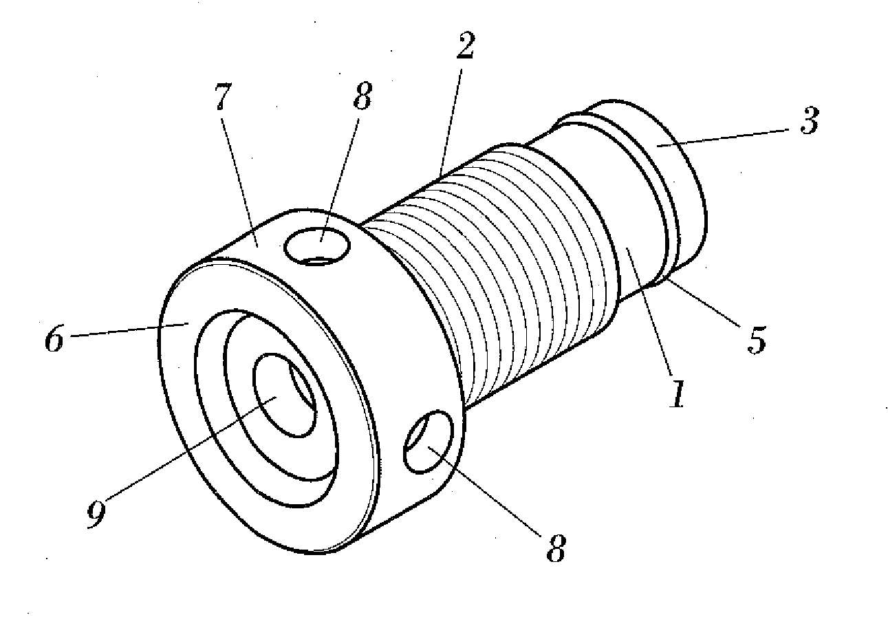
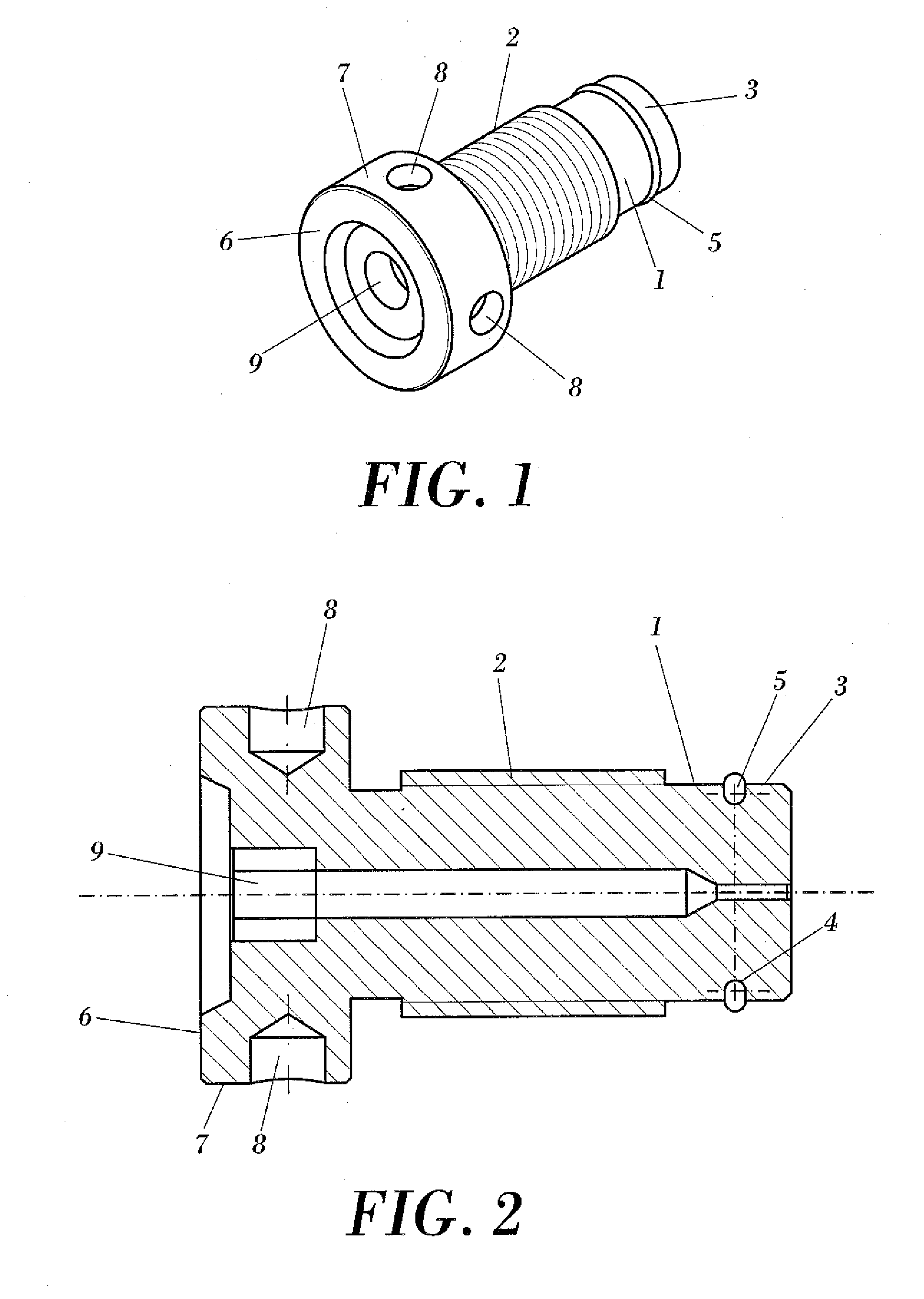
[0001]The present invention relates to a quick-assembly breech plug for muzzleloader firearms, applicable in the arms industry, and more specifically in the field of firearms for use in sports, allowing a quick and effective assembly and disassembly of the breech plug in the rear end of the barrel, being an extremely practical breech plug which is simple to manufacture and has a low cost, which allows its coupling in the barrel from any angular position.

Problems solved by technology

The main drawback of these breech plugs is that their manufacture is complicated and expensive, since the machining of said recessed grooves and bevel edges in the previously threaded male body of the breech plug is required, in addition to having to precisely incorporate recesses and complementary toothing inside the barrel, requiring the breech plug to be in a certain angular position before introducing it in the barrel, which delays the operations for assembling it, which furthermore require the use of suitable tools for screwing and unscrewing the breech plug.
US-2006 / 0248771-A1 relates to a muzzleloader firearm comprise a breech plug for quickly assembling the breech plug in the barrel, being based on a bayonet-type system, which incorporates teeth and grooves both in the barrel and in the breech plug configured to allow a coupling and uncoupling by means of 90° rotations, having as a drawback, in addition to those indicated above, the fact that considering the described coupling means it is extremely difficult to prevent firing gases from escaping through said clearances.

Method used


Image

  • Quick-assembly breech plug for muzzleloader firearms
  • Quick-assembly breech plug for muzzleloader firearms
  • Quick-assembly breech plug for muzzleloader firearms

Examples


Embodiment Construction

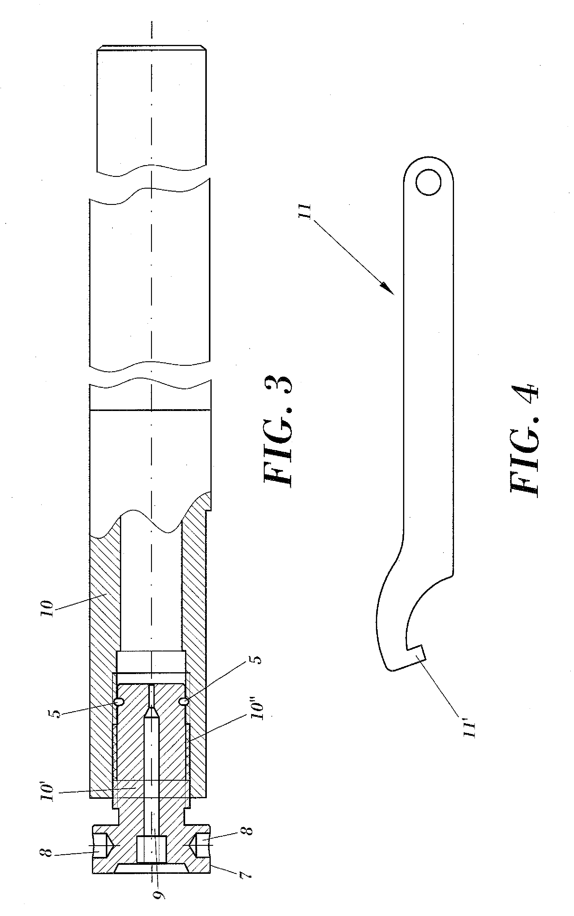
[0007]The present invention relates to a quick-assembly breech plug for muzzleloader firearms, which allows both assembling and disassembling the breech plug in the barrel in an extremely quick and effective manner, for the purpose of removing the breech plug to clean the loader or to remove a charge housed in the barrel. Said quickness and effectiveness are based on the breech plug of the invention requiring for its assembly and / or disassembly a smaller number of rotations in comparison with the currently existing breech plugs, the thread of which has a single start. The breech plug of the invention is simple, practical and inexpensive to manufacture, not requiring complex means for coupling to the barrel, as in the case of bayonet-type couplings, and allowing its introduction from any angular position, without having to be in a certain angular position for its introduction.

[0008]The quick-assembly breech plug for muzzleloader firearms proposed by the invention comprises a cylindri...


PUM


Abstract

The invention relates to a quick-assembly breech plug for muzzleloader firearms, allowing a quick assembly and disassembly and being extremely practical, simple to manufacture and having a low cost, wherein said breech plug comprises a cylindrical body (1), configured to be internally coupled in a rear end (10′) of a barrel (10), and a head (6) configured to define a limit coupling position of the breech plug inside the barrel (10), wherein the cylindrical body (1) externally comprises a male thread (2) having at least two starts located close to a front end (3) of the breech plug, opposite the head (6), according to a plane perpendicular to an axis of revolution of the cylindrical body (1), said male thread (2) being configured to screw into a female thread (10″) located internally in the rear end (10′) of the barrel (10), preferably 4 screw ridges.

Description

OBJECT OF THE INVENTION[0001]The present invention relates to a quick-assembly breech plug for muzzleloader firearms, applicable in the arms industry, and more specifically in the field of firearms for use in sports, allowing a quick and effective assembly and disassembly of the breech plug in the rear end of the barrel, being an extremely practical breech plug which is simple to manufacture and has a low cost, which allows its coupling in the barrel from any angular position.BACKGROUND OF THE INVENTION[0002]Firearms which are loaded through the muzzle of the firearm, usually known as muzzleloader firearms, incorporate at the rear end of the barrel, opposite the muzzle, a part referred to as breech plug which can be disassembled from the barrel, having the functions of closing the rear end of the barrel during its use, while at the same time it allows the ignition of the charge, likewise allowing accessing the inside of the barrel when it is disassembled for the purpose of performin...

Claims


Application Information

Patent Timeline
Patent Type & Authority Applications(United States)
IPC IPC(8): F41C9/08
CPCF41C9/08F41A3/74
Inventor CALVETE ZUMALDE, ANGEL
Owner ARDESA
Learn More