Ceiling Fan With High Efficiency Ceiling Fan Blades

Inactive Publication Date: 2009-10-22
KING OF FANS
View PDF23 Cites 18 Cited by
  • Summary
  • Abstract
  • Description
  • Claims
  • Application Information

AI Technical Summary

Benefits of technology

[0020]For the purpose of summarizing this invention, this invention comprises a ceiling fan having high efficiency fan blades. More particularly, several embodiments of the high efficiency fan blades of the invention each comprise a thin-edge configuration that effectively reduces thickness of the leading edge of prior art ceiling fan blades such that the thinner leading edge of the invention presents less resistance and produces less turbulence than thicker prior art fan blade edges. The thin-edge fan blades of the invention therefore result in high efficiencies.
[0022]Importantly, the thin leading edge of the invention is easily adapted to all types of ceiling fan blades that are currently being manufactured. For example, in the case of plastic fan blades, the thin edge design of the invention may be easily injection molded. In the case of plywood fan blades and MDF fan blades, the edge of the fan blade may be easily routed to the desired thin edge design and then sealed with a waterproof sealer painted onto the exposed edges.
[0023]In another embodiment of the high efficiency ceiling fan blades of the invention, the upper surface of the ceiling fan blades may comprise a generally apex configuration defined by two planar surfaces formed at an angle leading from the opposing thin leading edges across the width of the fan blade to form an apex along a center line of the fan blade. Importantly, the thickness of the fan blade at the thin leading edges comprises a reduced thickness which is equal to or appreciably greater than the minimum thickness mandated by applicable ceiling fan safety regulations. It is noted that the thin leading edge of this embodiment of the invention is contemplated to be principally formed by plastic injection molding or through carved fan blades due to the angles involved that could not typically be achieved through the use of laminated plywood or MDF. Indeed, this second embodiment is particularly desirable for implementation with decorative plywood or carved wood fan blades that would normally require significant sanding or carving to achieve the desired decorative designs. Moreover, the apex configuration provides strength along the longitudinal length of the fan blade thereby reducing the likelihood of drooping due to gravity over extended periods of non-use.
[0025]In both of these embodiments, the sheeting protects all or substantially all of the thin leading edge of the fan blade from moisture intrusion along the thin leading edge that would otherwise potentially result in swelling or warping of the fan blade. It is noted that in the embodiment in which the sheeting does not wrap around the thin leading edge to overlap similar sheeting on the other side, the exposed rounded leading edge of the fan blade is nevertheless coated with moisture-barrier paint or the like, thereby precluding moisture instruction along the thin edge of the blade. In both embodiments, the fact that the sheeting extends over all, or at least a significant portion of the edge, presents an extremely aesthetically clean appearance to the consumer over what would otherwise be observed by the consumer if the thin leading edge was not at all covered by the sheeting.

Problems solved by technology

Unfortunately, however, since plastic is typically heavier than plywood or MDF, plastic fan blades result in higher resistance to the electric motor thereby necessitating increased torque.
Unfortunately, however, the thick rounded leading edges of conventional fan blades produce a significant air resistance and turbulence as the ceiling fan blades are rotated through the air to cause the desired air flow.
The increased resistance and turbulence along the leading edge of the thick rounded leading edge of the fan blade appreciably reduces the efficiency of the ceiling fan.
In the case of the thicker plastic blades, even greater inefficiencies are often experienced.
Efforts to produce thinner blades that would correspondingly have thinner rounded edges, have met with little success since thinner blades do not have the necessary strength to function properly during continued use without droopage.
Moreover, prior art techniques for “beveling” the leading edge of a ceiling fan blade, such as taught by Taiwan Patent Application 79200819, filed Jan. 22, 1990, the disclosure of which is hereby incorporated by reference herein, have not met with any commercial success.
More particularly, beveling the leading edge of a ceiling fan blade such as taught by the Taiwanese patent application produces a relatively sharp knife edge that creates a hazardous condition in the event a person's hand or other object is moved into the path of the spinning fan blades.
However, this patent does not address the safety issues.
Unfortunately, like planar fan blades, curvilinear fan blades still produce appreciable resistance and turbulence along their leading edges.

Method used


Image

  • Ceiling Fan With High Efficiency Ceiling Fan Blades
  • Ceiling Fan With High Efficiency Ceiling Fan Blades
  • Ceiling Fan With High Efficiency Ceiling Fan Blades

Examples


Embodiment Construction

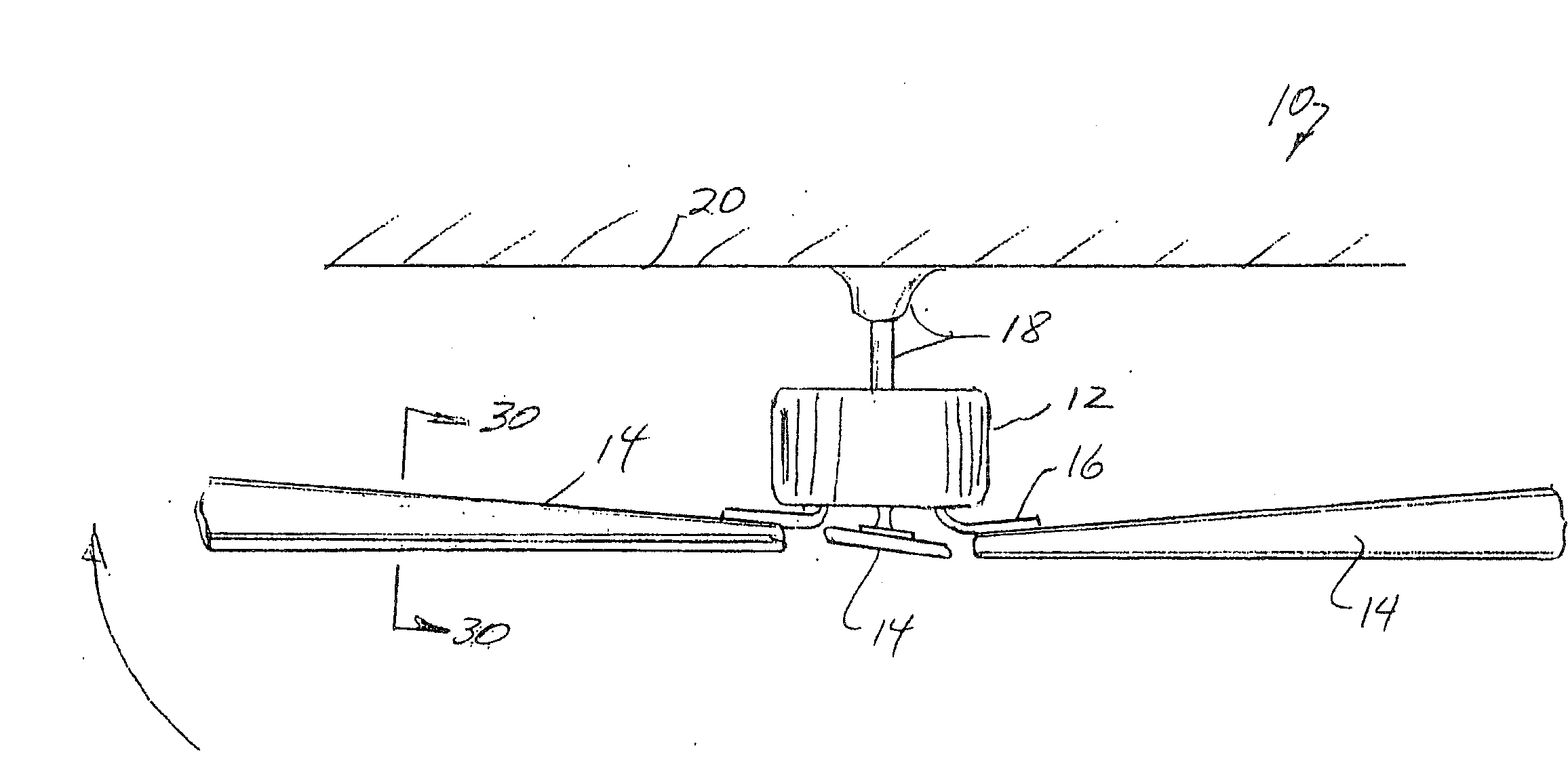
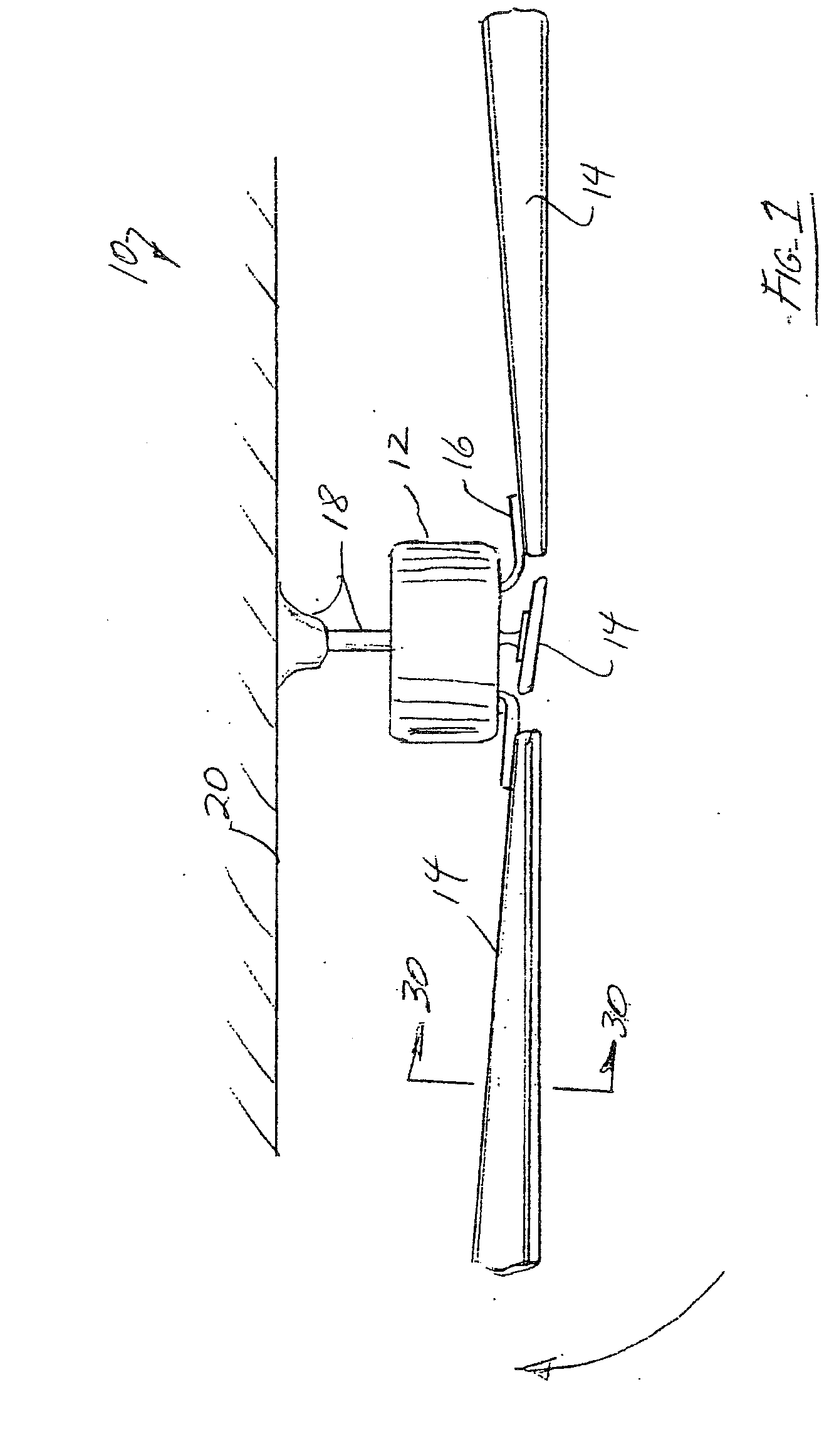
[0054]FIG. 1 is a side elevational view of a conventional ceiling fan 10 comprising an electric motor assembly 12 and a plurality of ceiling fan blades 14 connected to the rotor of the motor assembly 12 by means of ceiling blade brackets 16. The ceiling fan 10 is intended to be connected by means of a hanger and down rod assembly 18 to the ceiling 20 of a room. During operation in one direction, the rotating ceiling fan blades 14 circulate air downwardly from the ceiling 20 (typically during summer months). During operation in the reverse direction, the rotating ceiling fan blades 14 circulate air upwardly toward the ceiling 20 (typically during winter months). In either direction, the objective is to create a circulatory flow of air throughout the room to thereby reduce energy costs.

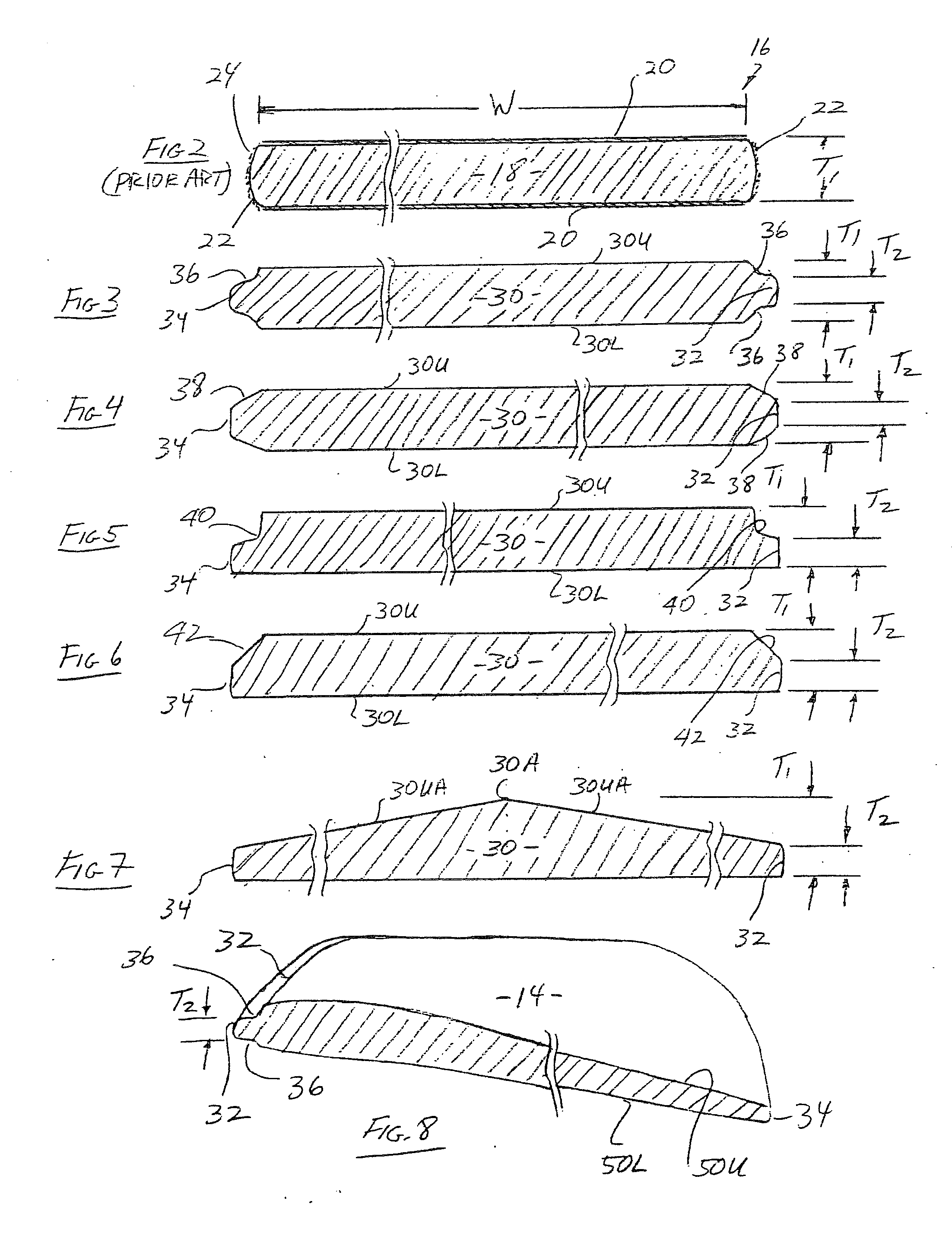
[0055]FIG. 2 is a cross sectional view of a conventional ceiling fan blade 16 manufactured from an MDF material. More particularly, an MDF fan blade 16 comprises a generally planar elongated configurati...


PUM

PropertyMeasurementUnit
Thicknessaaaaaaaaaa
Electrical resistanceaaaaaaaaaa
Widthaaaaaaaaaa

Abstract

A ceiling fan including a motor having a rotatable rotor, a plurality of ceiling fans blades having a thickness, the blades connected to the rotor to rotate therewith and each of the ceiling fan blades comprising a thin edge along its leading edge that is thinner than the thickness of the ceiling fan blade to present less resistance and produce less turbulence and achieve high efficiencies.

Description

CROSS-REFERENCE TO RELATED APPLICATIONS[0001]This application is a continuation of U.S. Ser. No. 11 / 430,260, filed May 8, 2006 which is a continuation-in-part application of U.S. Ser. No. 11 / 326,255, filed Jan. 5, 2006, the disclosures of which are hereby incorporated by reference herein.BACKGROUND OF THE INVENTION[0002]1. Field of the Invention[0003]This invention relates to ceiling fans. More particularly, this invention relates to ceiling fan blades having a high-efficiency design.[0004]2. Description of the Background Art[0005]Presently, there exist numerous types of ceiling fans designed to be suspended from a ceiling for circulating air flow within the room. Typically, ceiling fans comprise a plurality of ceiling fan blades which are operatively connected to an electric motor for rotating the fan blades to produce the desired air flow. The components of the ceiling fan, particularly the ceiling fan blades, are designed to optimize the amount of air flow being circulated per wa...

Claims


Application Information

Patent Timeline
IPC IPC(8): F04D29/38F04D25/02B23P15/04
CPCF04D25/088Y10T29/49337F04D29/384F04D29/023F05D2240/301F05D2240/303F05D2300/42F05D2300/43Y02T50/60
Inventor BUCHER, JOHN C.
Owner KING OF FANS
Why Eureka
Try Eureka