Micromechanical part with an opening for fastening to a spindle
- Summary
- Abstract
- Description
- Claims
- Application Information
AI Technical Summary
Benefits of technology
Problems solved by technology
Method used
Image


Examples
first embodiment
[0034]FIG. 3 partially shows a micromechanical part according to the invention. This micromechanical part is flat and thin and comprises an opening 10 intended to accommodate a spindle (not shown). Rigid areas 11 and elastic areas 12 alternate over the edges of the opening 10.
[0035]The rigid areas 11 are each formed by a convex portion projecting from the micromechanical part in the direction of the center of the opening 10, this center being depicted in FIG. 3 by a point C. The contour of each rigid area 11 is that of a circular arc. All the rigid areas 11 are identical to one another and, by connecting their ends 13 closest to the point C of the opening 10, a first circle C1 is obtained whose center is coincident with the point C.
[0036]The elastic areas 12 are each formed by an arm which is curved toward the point C. Each arm has the shape of a ring segment projecting from the micromechanical part toward the point C and in which the largest-diameter side is directed toward the poi...
second embodiment
[0041]FIG. 4 partially shows a micromechanical part according to the invention. This micromechanical part is likewise flat and thin.
[0042]The rigid areas 11 are similar to those of the first embodiment and do not therefore need to be described again.
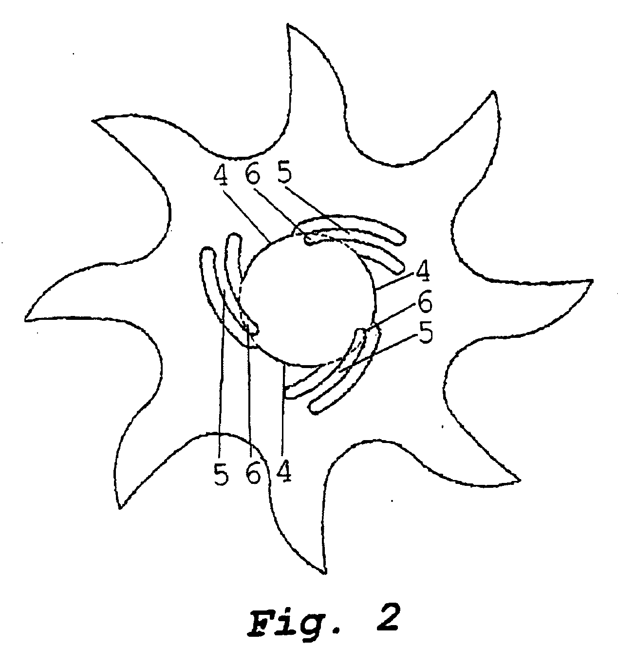
[0043]The difference between this embodiment and the first lies essentially in the shape of the elastic areas. Specifically, in this second embodiment, each elastic area 22 is formed by two curved fingers 22a, 22b.
[0044]Each finger 22a substantially has the shape of a ring projecting from the micromechanical part and from which a section has been removed in order to form a space 23a. Similarly, each finger 22b substantially has the shape of a ring projecting from the micromechanical part and from which a section has been removed in order to form a space 23b.
[0045]The spaces 23a and 23b of the fingers 22a and 22b of one and the same area 22 are not directed toward the point C: they are situated between the free end 27 of the ring and th...
third embodiment
[0051]FIG. 5 partially represents a micromechanical part according to the invention. This micromechanical part is in turn also flat and thin.
[0052]The rigid areas 11 are similar to those of the preceding embodiments and therefore do not need to be described again.
[0053]The difference between this embodiment and the previous ones lies essentially in the shape of the elastic areas. Specifically, in this third embodiment, each elastic area 32 is formed by two substantially rectilinear half-arms 32a, 32b. Each half-arm 32a projects from the micromechanical part in a direction forming a slight angle (less than 10 degrees) with a tangent to the circle C1 passing through a point situated midway between the two half-arms 32a, 32b. Hence, its free end 33a is situated closer to the point C, which symbolizes the center of the opening 30.
[0054]Similarly, each half-arm 32b of the same area 32 projects from the micromechanical part in a direction forming a slight angle (less than 10 degrees) with...
PUM
| Property | Measurement | Unit |
|---|---|---|
| Pressure | aaaaa | aaaaa |
| Pressure | aaaaa | aaaaa |
| Pressure | aaaaa | aaaaa |
Abstract
Description
Claims
Application Information
 - R&D
- Intellectual Property
- Life Sciences
- Materials
- Tech Scout
- Unparalleled Data Quality
- Higher Quality Content
- 60% Fewer Hallucinations
Browse by: Latest US Patents, China's latest patents, Technical Efficacy Thesaurus, Application Domain, Technology Topic, Popular Technical Reports.
© 2025 PatSnap. All rights reserved.Legal|Privacy policy|Modern Slavery Act Transparency Statement|Sitemap|About US| Contact US: help@patsnap.com