Method and Apparatus For Automating Production of Sinuous Springs

Active Publication Date: 2009-10-22
L & P PROPERTY MANAGEMENT CO
View PDF26 Cites 11 Cited by
  • Summary
  • Abstract
  • Description
  • Claims
  • Application Information

AI Technical Summary

Benefits of technology

[0008]The slide block has a pair of cam blocks and a pair of guide pins attached thereto. The cam blocks have slots therein for guiding an overbend tool assembly, the guide pins being retained in the overbend tool assembly for further guiding said overbend tool assembly. The adjustment apparatus further comprises a cover with a slot therein thorough which a portion of the overbend tool assembly passes to provide a stop for the wire. The adjustment apparatus further comprises a guide cover and a pair of clamp assemblies for securing the guide cover in place. During operation, the sinuous wire passes under the guide cover and over the cover. The machine comprises lubrication means to keep the machine components lubricated to help the continuous length of sinuous spring wire move through the forming apparatus smoothly and withing binding until it passes to an accumulator.
[0011]Another way to describe this method is as follows: a method of manufacturing sinuous springs, each sinuous spring comprising a discrete strip of sinuous spring wire having parallel bar segments interconnected at their opposite ends by oppositely directed connecting segments. The method comprises first providing a machine for manufacturing sinuous springs of the same length and then adding an adjustment apparatus to the machine so an operator may adjust the length of the sinuous springs by turning a handle. The adjustment apparatus changes the position of an overbend tool adjustable during operation of the machine to change the position of the parallel bar segments relative to the connecting segments. Using this method to retrofit an existing machine enables an operator to change the length of the sinuous springs exiting the punch press without stopping or interrupting the operation of the machine. Allowing the machine to operate continuously improves the productivity and efficiency of the machine while reducing the need for a skilled operator to adjust the machine.

Problems solved by technology

Each time the operator stopped the machine, the machine was not producing resilient sinuous spring elements.
This reduced the output of the machine and required skilled operators to properly adjust the machine.

Method used


Image

  • Method and Apparatus For Automating Production of Sinuous Springs
  • Method and Apparatus For Automating Production of Sinuous Springs
  • Method and Apparatus For Automating Production of Sinuous Springs

Examples


Embodiment Construction

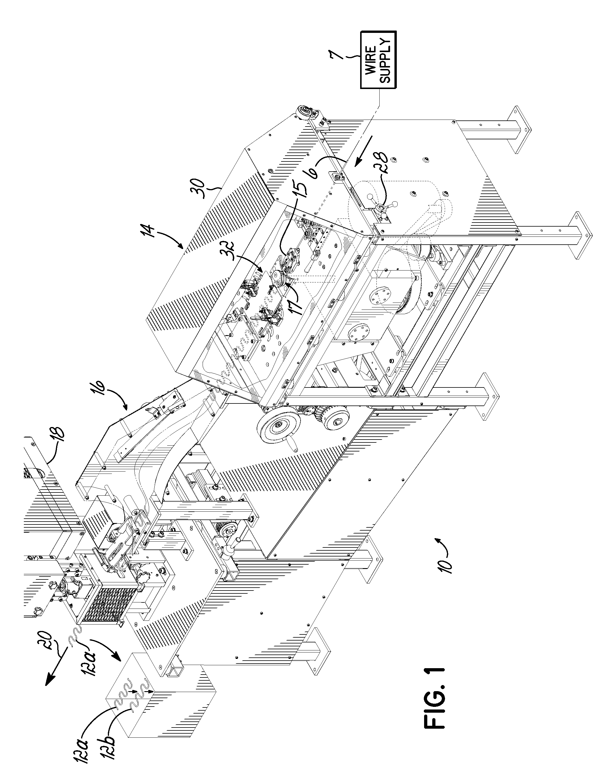
[0037]Referring to the figures, and particularly, to FIG. 1, there is illustrated a machine 10 for manufacturing a plurality of sinuous springs 12. The machine 10 has three principal components: a forming apparatus 14, an accumulator 16 downstream of the forming apparatus 14 and a punch press 18 downstream of the accumulator 16 (the flow of wire is generally indicated by the arrow 20).

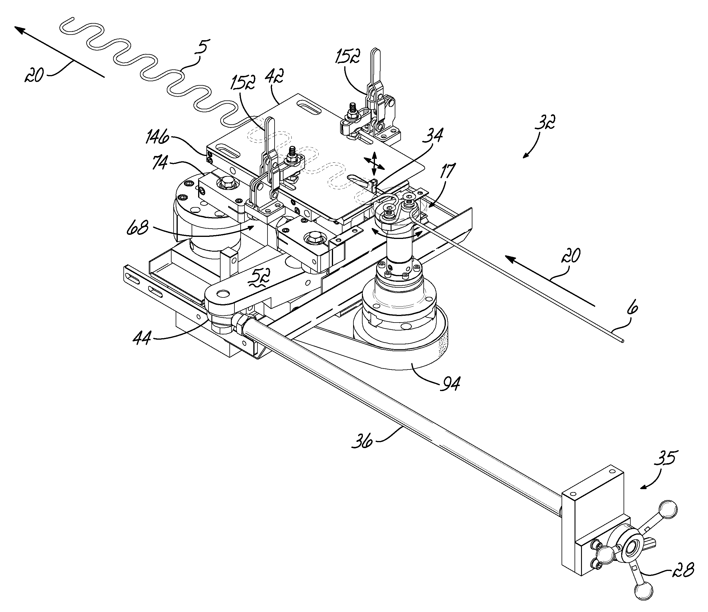
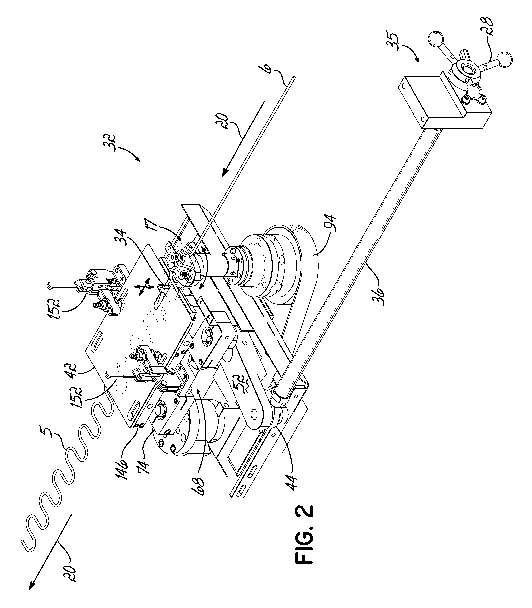
[0038]The forming apparatus 14 enables sinuous springs 12a, 12b to exit the downstream end of the machine 10 of different lengths without turning off or shutting down the machine 10 to make manual adjustments to it. Instead, an adjustment apparatus 32, shown in an assembled condition in FIG. 2, and disassembled in FIG. 5, has been incorporated into the machine 10. More particularly, the adjustment apparatus 32 has been incorporated into the forming apparatus 14 of the machine 10 to enable sinuous springs of different lengths to be produced on the machine 10 without stopping the machine 10. As best show...


PUM

PropertyMeasurementUnit
Lengthaaaaaaaaaa

Abstract

A method and apparatus is disclosed for manufacturing sinuous springs wherein each spring comprises a discrete length of sinuous spring wire having parallel straight bar segments interconnected at their opposite ends by oppositely directed curved connecting segments. This apparatus is operable to adjust the length of the sinuous spring wires exiting the machine without turning off or stopping the machine. An operator need only rotate a handle outside a housing of the machine to increase or decrease the length of the sinuous spring wires exiting the machine.

Description

FIELD OF THE INVENTION [0001]This invention relates generally to sinuous wire springs and, more particularly, to a method and apparatus for producing sinuous wire springs.BACKGROUND OF THE INVENTION [0002]Many furniture products, including such products as chairs, sofas and automobile seats utilize sinuous wire spring elements as to create resilient surfaces, such as seats and backrests, in an item of furniture. Such resilient spring elements are disclosed, for example, in U.S. Pat. No. 6,263,573. Each resilient sinuous spring element has a plurality of straight bar portions joined by a plurality of connecting or curved or radiused portions. Generally, these sinuous spring elements are manufactured on a machine which produces a quantity of identical sinuous springs, each sinuous spring having the same number of straight bar portions and the same radius in its curved portions. Therefore, each resilient sinuous spring element has the same length. The machine had to be stopped and adju...

Claims


Application Information

Patent Timeline
IPC IPC(8): B21F11/00B21D31/00
CPCB21F1/04
Inventor KNEWTSON, KELLY M.
Owner L & P PROPERTY MANAGEMENT CO
Why Eureka
Try Eureka