
Method and/or device for controlling and/or monitoring the movement of industrial machines

a technology for industrial machines and monitoring devices, applied in the field of industrial machine operation, can solve problems such as the risk of increasing unproductive periods

Inactive Publication Date: 2009-10-15
SIEMENS AG
View PDF2 Cites 88 Cited by
  • Summary
  • Abstract
  • Description
  • Claims
  • Application Information

AI Technical Summary

Benefits of technology

[0014]It is an object of the present invention to provide a method and a device which gives a better simulation of dynamic and / or static processes in an industrial machine and / or improves the use of the industrial machine through a simulation.
[0047]In a further embodiment of the device according to the invention, said device has means for visualizing the movement and / or the visualized position of at least one free body, wherein the visualization can be carried out, in particular, in real time. By this means, for example, an operator of an industrial machine can observe in real time on an HMI (human machine interface) the simulated movement of free bodies within or on the industrial machine without the need for a camera. Not only does this reduce the costs, it is also advantageous in areas where the environmental conditions make the operation of cameras difficult (e.g. due to excessive temperatures). Advantageously, the device according to the invention is used in a method according to the invention.

Problems solved by technology

In the production of goods (e.g. plastics injection molded parts) and / or services (e.g. transport by a crane), the following trends are becoming increasingly apparent:more complex, highly automated production machines and production equipment (e.g. printing machines)risk of increasing unproductive periods, for example, for planning, design, commissioning, optimizing

Method used


Image

  • Method and/or device for controlling and/or monitoring the movement of industrial machines
  • Method and/or device for controlling and/or monitoring the movement of industrial machines
  • Method and/or device for controlling and/or monitoring the movement of industrial machines

Examples


Embodiment Construction

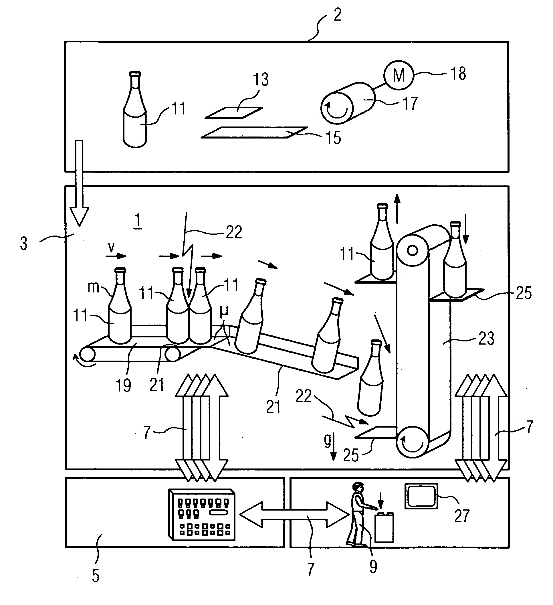
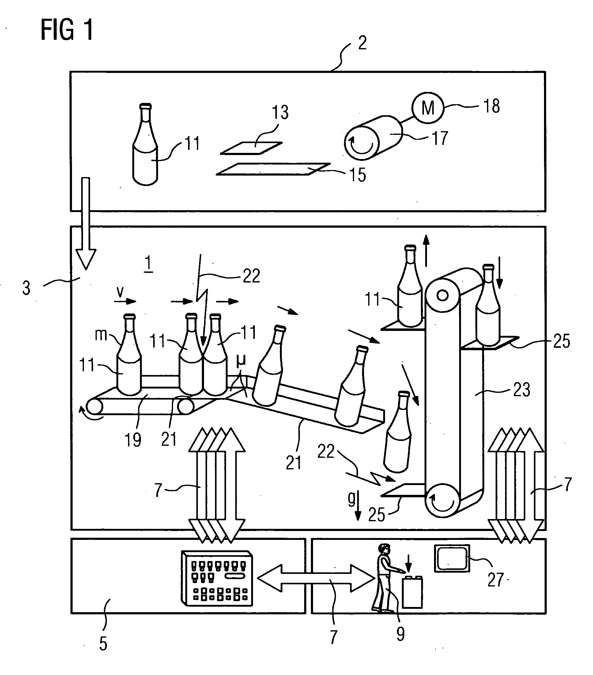
[0051]The representation in FIG. 1 shows the modeling and simulation of a transport apparatus for bottles 11. A transport apparatus 1 of this type for bottles 11 is an industrial machine and is used, for example, in a bottle filling apparatus. The bottle filling apparatus is also an example of an industrial machine. In a first step 2 of the method, the parameters for the simulation are defined. This relates, for example, to the geometry of the bottle 11. Apart from the geometry of the bottle 11, for example, the density ρ of the material or its Young's modulus is also stipulated.

[0052]Furthermore, the coefficients of friction μ, in particular, are also stipulated. For this purpose, in an advantageous embodiment, the points of application of the forces and other boundary conditions are also determined. The coefficients of friction μ relate both to a surface 13 of a base of the bottle 11 and to a surface 15 of a conveyor belt, wherein both are symbolized by one surface.

[0053]The conve...


PUM


Abstract

There is described a method for controlling and / or monitoring a movement of a free body in an industrial machine, wherein the industrial machine comprises an actuator for carrying out a movement, wherein the movement of at least one free body is either mechanically coupled to the movement of the actuator and / or is decoupled from the movement of the actuator. At least one of the following physical variables of the free body: weight, density, frictional parameters, geometric form and / or center of gravity is input into a simulation program, whereupon with the aid of at least one of these physical variables, the movement of the free body is simulated, wherein the simulation takes place, in particular, in real time. This enables a better simulation of dynamic and / or static processes in an industrial machine.

Description

CROSS REFERENCE TO RELATED APPLICATIONS[0001]This application is the US National Stage of International Application No. PCT / EP2006 / 064947, filed Aug. 2, 2006 and claims the benefit thereof. The International Application claims the benefits of German application No. 10 2005 043 022.8 DE filed Sep. 9, 2005, both of the applications are incorporated by reference herein in their entirety.FIELD OF INVENTION[0002]The present invention relates to a method for operating an industrial machine and for simulating the operation of an industrial machine. An industrial machine may be, for example, a machine tool, an automatic handling device or a production machine. Machine tools are provided, for example, for the processing of workpieces. The processing involves, for example, turning, milling and / or grinding of a workpiece. These types of processing in machine tools can therefore be either cutting or non-cutting. Examples of production machines are plastics injection molding machines, bag formin...

Claims


Application Information

Patent Timeline
Patent Type & Authority Applications(United States)
IPC IPC(8): G06G7/66G06F17/10
CPCG05B2219/32342G05B19/4069Y02P90/02
Inventor DOLANSKY, STEFANSCHNEIDER, ROLAND
Owner SIEMENS AG
Learn More