
Portable electronic apparatus and housing thereof

a technology of electronic equipment and housing, which is applied in the direction of electrical equipment casings/cabinets/drawers, electrical equipment construction details, instruments, etc., can solve the problems of flat housing body damage, embedded electronic devices such as camera modules and camera lenses thereof, and achieve the effect of improving rigidity and strength of portable electronic equipment and minimizing the likelihood of damag

Active Publication Date: 2009-10-15
HTC CORP
View PDF3 Cites 1 Cited by
  • Summary
  • Abstract
  • Description
  • Claims
  • Application Information

AI Technical Summary

Benefits of technology

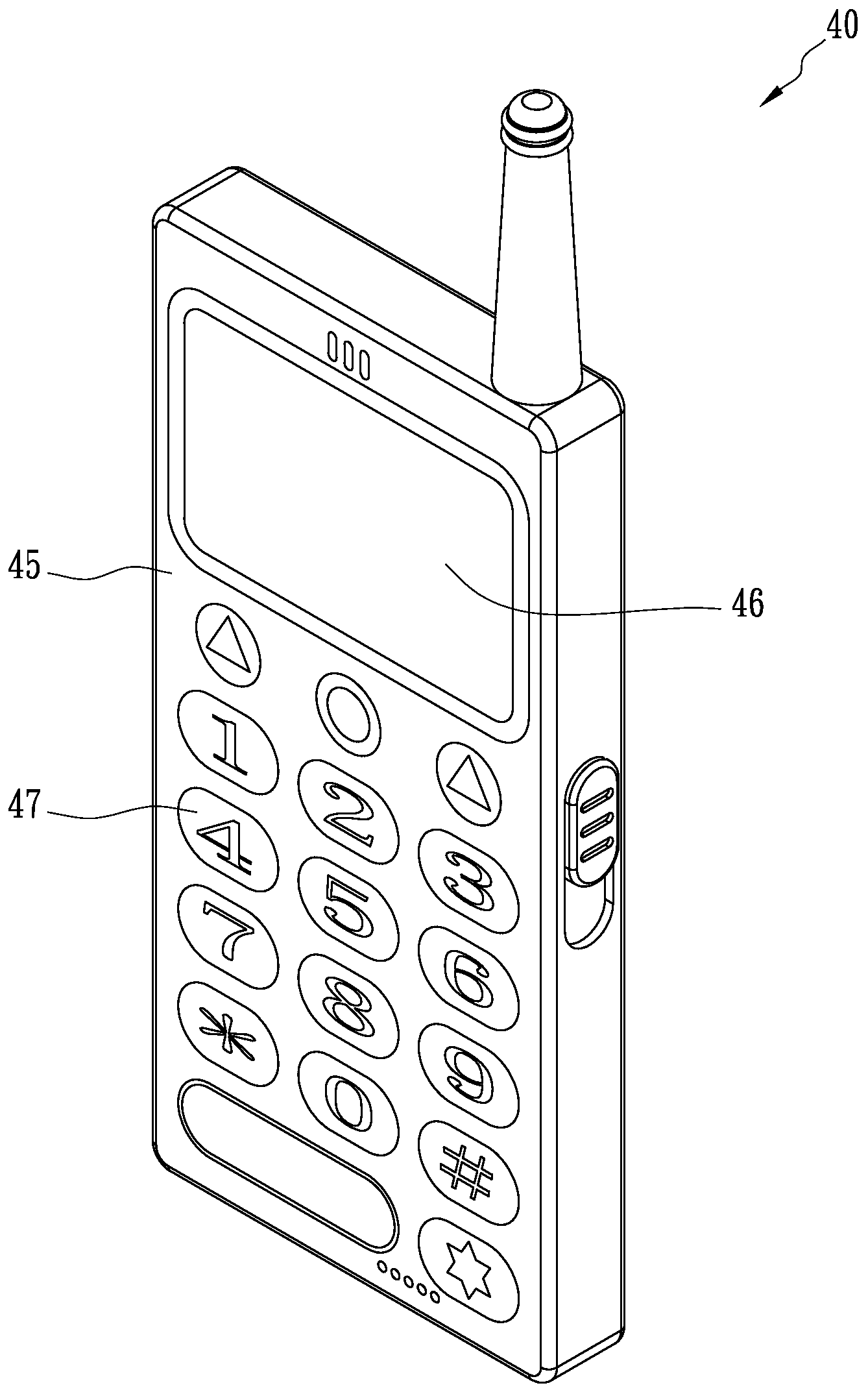
[0007]The present invention provides a portable electronic apparatus and the housing thereof with a rear side, which has at least three facets to form at least one peak. The rear side with the facets can withstand an impact to the portable electronic apparatus so as to prevent electronic devices embedded in the portable electronic apparatus from being damaged.
[0009]According to force equilibrium of static mechanics, a force applied to the peak of the rear side will be withstood by plural forces each with a small amount. Therefore, the rear side with the peak is not easily damaged.
[0010]A housing of the portable electronic apparatus comprising the above-mentioned rear side is also covered by the scope of the present invention. In an embodiment, one or more peaks are formed on the rear side of the portable electronic apparatus, so that an electronic device, e.g., a digital camera module, embedded in the rear side can be well protected to minimize the likelihood of damage.
[0011]In accordance with the present invention, the mechanical properties such as rigidity and strength of the portable electronic apparatus can be significantly improved, and the housing with the facets described herein can share the forces and withstand the impact in a dropping test or a so-called choc test for testing endurance, such as a scratch test, in various situations.

Problems solved by technology

However, if the user drops the portable electronic apparatus, the flat housing body may be broken and the embedded electronic device such as a camera module and the camera lens thereof would be damaged.

Method used


Image

  • Portable electronic apparatus and housing thereof
  • Portable electronic apparatus and housing thereof
  • Portable electronic apparatus and housing thereof

Examples


Embodiment Construction

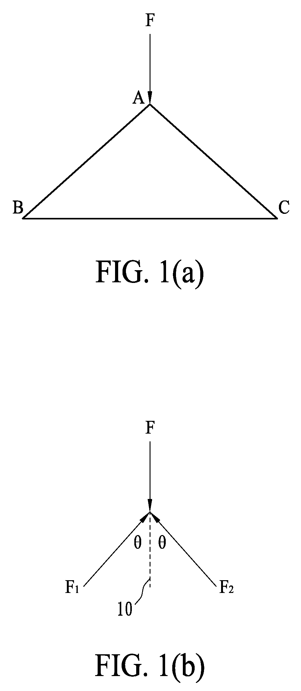
[0019]As shown in FIG. 1(a), a force F acts on a point of a rigid body, e.g., a peak A of a protrusion structure with two bottom corners B and C, and two forces F1 and F2 will be respectively generated along the inclined sides B to A and C to A of the protrusion structure as shown in FIG. 1(b). According to force equilibrium in static mechanics, F=F1 cos θ+F2 cos θ, where θ is the angle between F1 or F2 and a dotted line 10. In this embodiment, a force acting on the peak of a protrusion structure will be withstood by two forces each with a smaller amount. Therefore, the protrusion structure provides higher rigidity and can withstand a higher force or momentum impact in comparison with the traditional flat structure.

[0020]The present invention provides a portable electronic apparatus having at least one protrusion structure formed thereon to provide higher rigidity and strength such that the portable electronic apparatus can prevent the inner sophisticated or fragile electronic devic...


PUM


Abstract

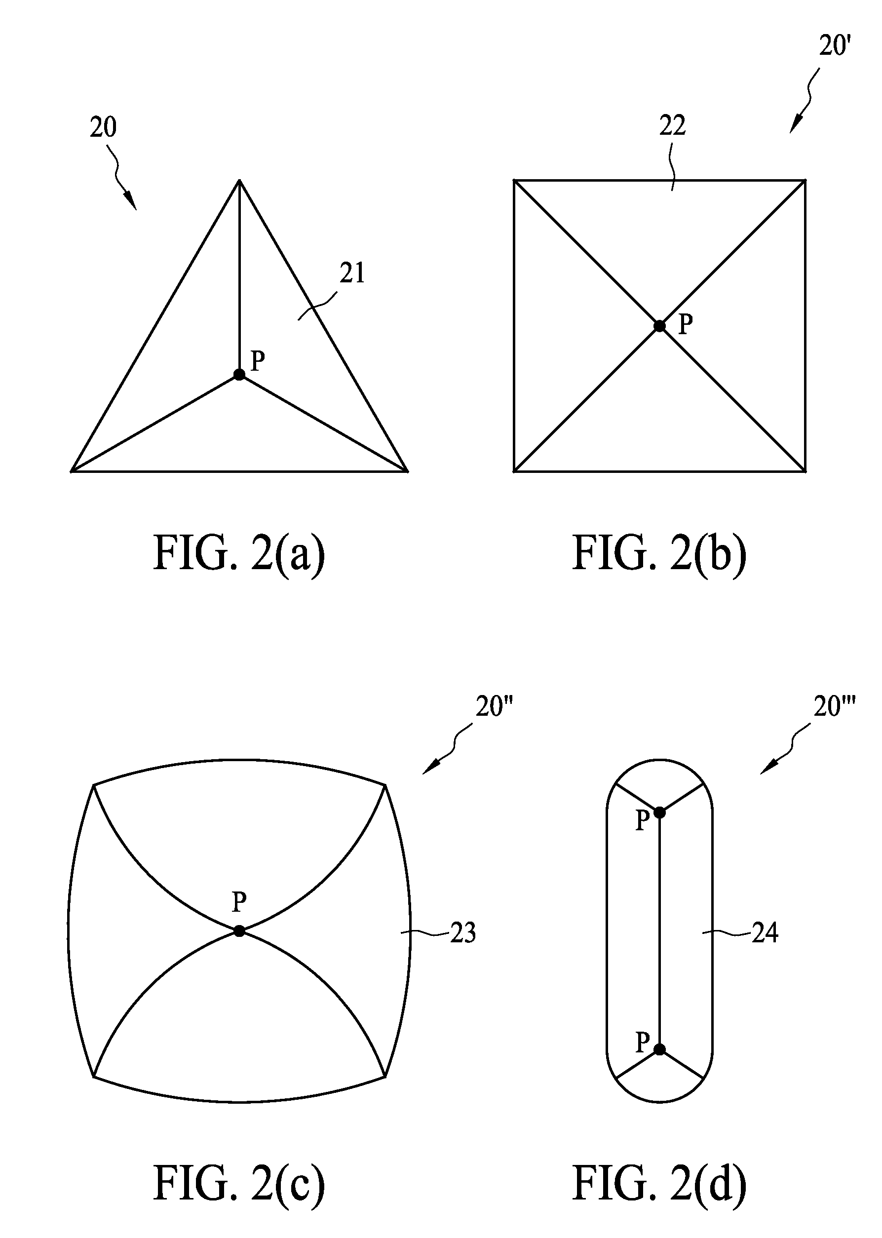
A portable electronic apparatus comprises one or more protrusion structures on a surface of the portable electronic apparatus. The protrusion structure comprises a plurality of facets, and one or more peaks are formed on the junctions of the facets. The facets are preferably in the form of triangles or quadrangles, and the protrusion structure is in the form of a pyramid of a triangular base or a quadrangular base. In an embodiment, the protrusion structure is formed on the back housing of the portable electronic apparatus, so that an electronic device, e.g., a digital camera module, embedded in the back housing can be protected to minimize the likelihood of damage.

Description

BACKGROUND OF THE INVENTION[0001](A) Field of the Invention[0002]The present invention is related to a portable electronic apparatus and housing thereof, and more specifically, to a portable electronic apparatus and housing thereof with high rigidity.[0003](B) Description of the Related Art[0004]Recently, portable electronic apparatuses, such as portable computers, cellular phones, smart phones and personal digital assistants (PDA), have been developed with multiple functions and a compact size. Further, display panels and keypads have been made with a very thin structure in order to enhance the compact size of portable electronic apparatuses, and a camera module installed in a portable electronic apparatus has become popular.[0005]Generally, such a portable electronic apparatus includes a flat housing body. However, if the user drops the portable electronic apparatus, the flat housing body may be broken and the embedded electronic device such as a camera module and the camera lens ...

Claims


Application Information

Patent Timeline
Patent Type & Authority Applications(United States)
IPC IPC(8): H04M1/00H05K5/00H05K7/00
CPCH04M1/0202H04M1/18H04M1/0264H04M1/185
Inventor CHIEN, CHIH LING
Owner HTC CORP
Learn More