
Time-interleaved analog-to-digital conversion apparatus

Inactive Publication Date: 2009-10-15
NOVATEK MICROELECTRONICS CORP
View PDF5 Cites 86 Cited by
  • Summary
  • Abstract
  • Description
  • Claims
  • Application Information

AI Technical Summary

Benefits of technology

[0010]The present invention is directed to a time-interleaved analog-to-digital conversion apparatus adapted to a television system. During analog-to-digital conversion of image signals, the analog-to-digital conversion apparatus may provide different gains for amplifying different kind of image signals, so as to increase each SNR thereof.
[0011]Embodiments of the present invention provide time-interleaved analog-to-digital conversion apparatuses, which may provide different gains for amplifying different image signals during analog-to-digital conversion of the image signals, so as to increase each SNR thereof.
[0021]According to the present invention, during the analog-to-digital conversion, different gains are applied to amplify different kind of signals. Therefore, the SNR during signal transmission may be effectively reduced, and accuracy of the signal may be improved.

Problems solved by technology

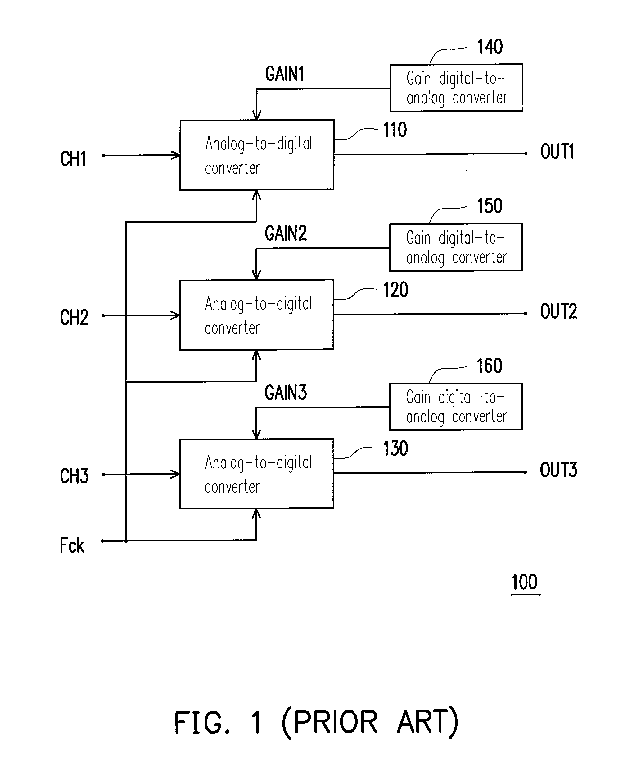
Since the analog-to-digital conversion apparatus 100 applies a plurality of the analog-to-digital converters 110, 120 and 130, relatively more circuits are applied in the apparatus, and therefore cost thereof is expensive.
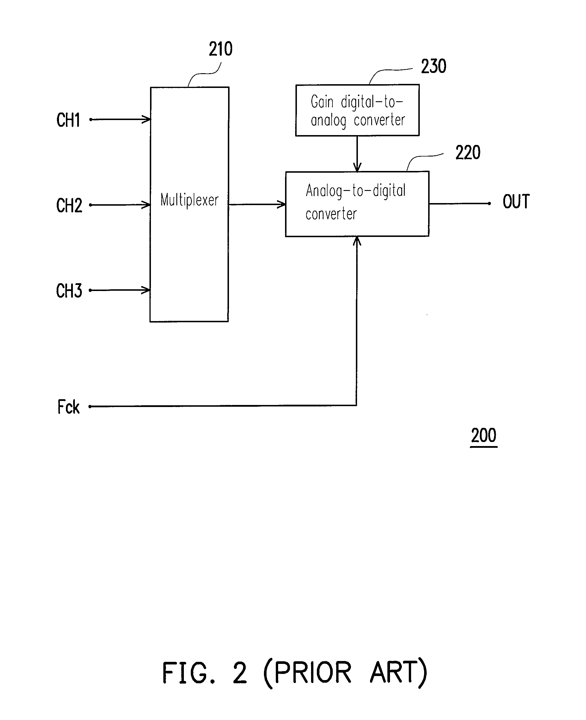
Limited by a bit number of the analog-to-digital converter 220, it is difficult for the same gain to effectively amplify three different image signals.
For example, when the luminance signal is relatively great, only a relatively small gain may be applied, so that the probably small chrominance signal cannot be effectively amplified, and therefore the SNR of the chrominance signal is quite low, or even the chrominance signal may be lost.

Method used


Image

  • Time-interleaved analog-to-digital conversion apparatus
  • Time-interleaved analog-to-digital conversion apparatus
  • Time-interleaved analog-to-digital conversion apparatus

Examples


Embodiment Construction

[0029]In the following content, a plurality of embodiments with reference of figures is provided to further describe the present invention, so as to fully convey the spirit of the present invention for those skilled in the art.

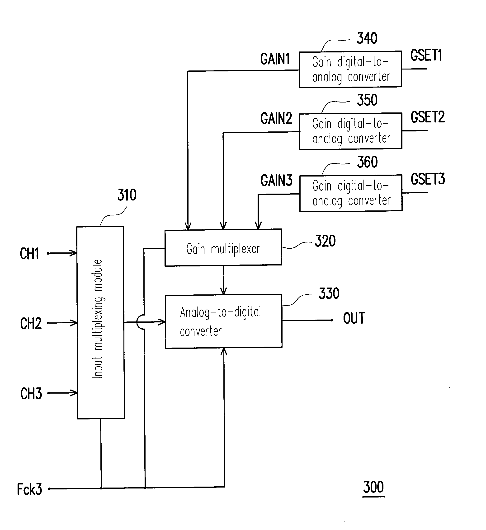
[0030]Referring to FIG. 3A, FIG. 3A is a block diagram illustrating a time-interleaved analog-to-digital conversion apparatus 300 according to an embodiment of the present invention. The analog-to-digital conversion apparatus 300 of the present invention is a time-interleaved analog-to-digital conversion apparatus, which may be applied to a television system (not shown in FIG. 3A) for processing image signals. However, such application is not intended to limit the present invention. The analog-to-digital conversion apparatus 300 includes an input multiplexing module 310, a gain multiplexer 320, an analog-to-digital converter 330 and a plurality of gain digital-to-analog converters 340˜360. The input multiplexing module 310 receives and samples the input signal...


PUM


Abstract

A time-interleaved analog-to-digital conversion apparatus is disclosed. The time-interleaved analog-to-digital conversion apparatus is applied for a television system and includes an input multiplexing module, a gain multiplexer and an analog-to-digital converter. The input multiplexing module receives a plurality of image signals, and samples the image signals according to a clock signal to generate a sample multiplexing signal. The gain multiplexer receives a plurality of gain signals and selectively transmits one of the gain signals corresponding to the sample multiplexing signal according to the clock signal, so as to generate a gain multiplexing signal. The analog-to-digital converter receives the sample multiplexing signal, the gain multiplexing signal and the clock signal. The analog-to-digital converter amplifies and converts the sample multiplexing signal to a digital signal according to the gain multiplexing signal and the clock signal.

Description

CROSS-REFERENCE TO RELATED APPLICATION[0001]This application claims the priority benefit of Taiwan application serial no. 97113615, filed on Apr. 15, 2008. The entirety of the above-mentioned patent application is hereby incorporated by reference herein and made a part of specification.BACKGROUND OF THE INVENTION[0002]1. Field of the Invention[0003]The present invention relates to an analog-to-digital conversion apparatus. More particularly, the present invention relates to a time-interleaved analog-to-digital conversion apparatus.[0004]2. Description of Related Art[0005]With development of technology, demanding of electronic products is increased accordingly. Besides good qualities and powerful functions of the electronic products, low prices thereof are also important references considered by consumers during purchasing. With quick development of fabrication abilities for electronic devices, working frequencies of the electronic devices are increased accordingly. Therefore, a conv...

Claims


Application Information

Patent Timeline
IPC IPC(8): H03M1/12
CPCH03M1/129H03M1/1225
Inventor WU, SHANG-HSIU
Owner NOVATEK MICROELECTRONICS CORP
Learn More