
Line connection structure for electric equipment and electric vehicle

a technology of electric equipment and connection structure, which is applied in the direction of electric propulsion mounting, electric devices, transportation and packaging, etc., can solve the problems of insufficient protection of cable connections the high-voltage cable may be caught between the front structure and the electric equipment, so as to increase the number of components

Inactive Publication Date: 2009-10-15
TOYOTA JIDOSHA KK
View PDF7 Cites 6 Cited by
  • Summary
  • Abstract
  • Description
  • Claims
  • Application Information

AI Technical Summary

Benefits of technology

[0014]An object of the present invention is to provide a line connection structure for electric equipment being capable of protecting a line while suppressing an increase in the number of components and being capable of preventing contact between the line and a further component in a normal mode even when the clearance between the electric equipment and the further component is narrow, and to provide an electric vehicle.
[0016]With the above-described configuration, even when the front structure deforms due to an external factor, the line can be prevented from being caught between the front structure and the electric equipment. Accordingly, it becomes possible to protect the line while suppressing an increase in the number of component. Additionally, since the width of the line in the vehicular front-rear direction can be narrowed, even when the clearance between the electric equipment and the further component is narrow, contact between the line and the further component in a normal mode can be avoided.
[0018]Thus, even when the electric equipment moves due to an external factor and the line is caught between the electric equipment and the further component, the further component can deform to thereby absorb the shock. As a result, the effect of protecting the line while suppressing an increase in the number of component can be enhanced.
[0020]It is important to avoid damage to such a line connected to the electric equipment for high voltage. With the above-described configuration, such a high-voltage line can be protected.
[0026]The radiator arranged along the front surface of the vehicle tends to move rearward due to an external factor such as front collision. By connecting the line from the vehicular rear side to the electric equipment, the line can be protected.
[0028]According to the present invention, as described above, a line connection structure for electric equipment being capable of protecting a line while suppressing an increase in the number of components and being capable of preventing contact between the line and a further component in a normal mode even when the clearance between the electric equipment and the further component is narrow can be obtained.

Problems solved by technology

In such a case, when a front structure of the electric equipment deforms due to an external factor such as front collision, the high-voltage cable may be caught between the front structure and the electric equipment.
Merely connecting the high voltage line to the lower surface of the electric equipment may be insufficient for protecting the cable.

Method used


Image

  • Line connection structure for electric equipment and electric vehicle
  • Line connection structure for electric equipment and electric vehicle
  • Line connection structure for electric equipment and electric vehicle

Examples


Embodiment Construction

[0040]In the following, an embodiment of the present invention will be described. The same or corresponding parts are denoted by the same reference character and description thereof may not be repeated.

[0041]In the embodiment described in the following, reference to the number or quantity does not necessarily limit the scope of the present invention to the exact number or quantity, unless otherwise specified. Also, in the following embodiment, constituents are not necessarily essential for the present invention, unless otherwise specified. When there are several embodiments in the following, combination of the configurations of the embodiments as appropriate is originally envisaged, unless otherwise specified.

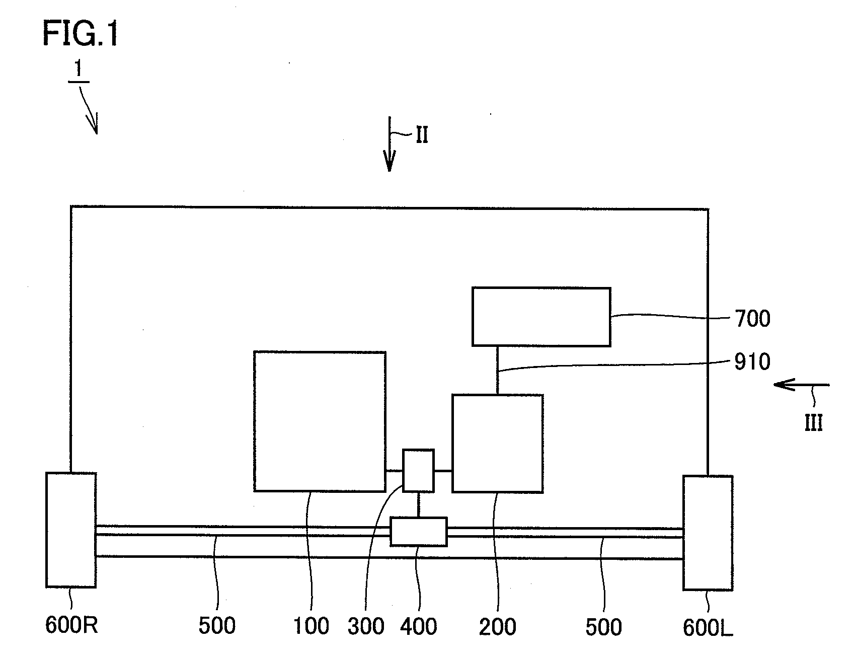
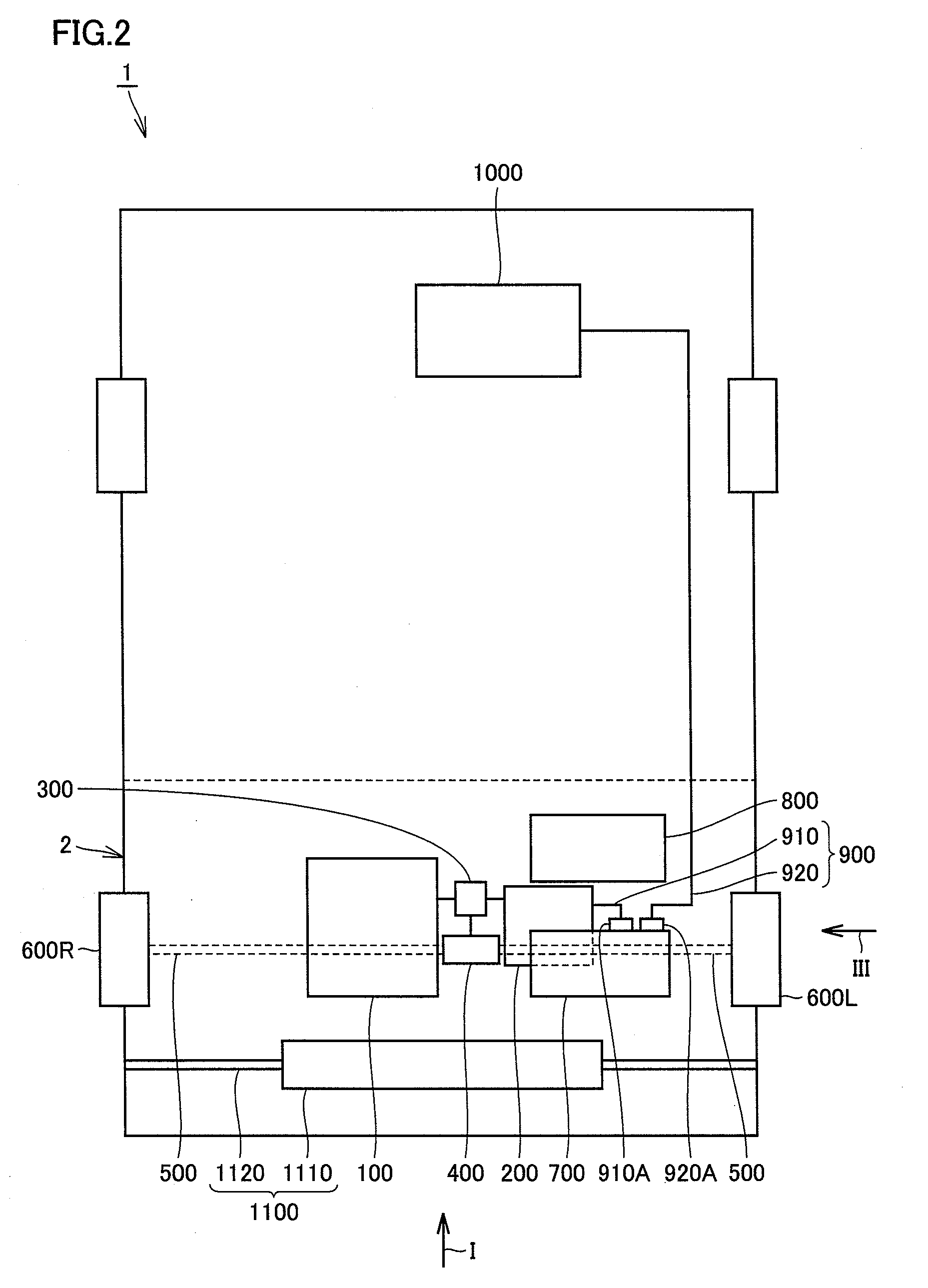
[0042]FIGS. 1-3 are schematic views showing a configuration of a hybrid vehicle having a line connection structure for electric equipment according to one embodiment of the present invention. FIGS. 1-3 respectively show the hybrid vehicle as seen from the directions of arrow I ...


PUM


Abstract

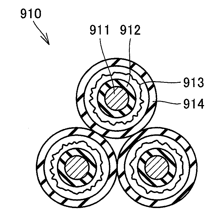
A line connection structure for a PCU includes: the PCU mounted in an engine room positioned on a front side of a hybrid vehicle; an air cleaner that is provided on a rear side of the vehicle so as to face the PCU and that includes a resin portion deforming easier than electric equipment; and a cable connected to the PCU. The cable is formed by three-phase cables of U, V, and W phases being gathered. The cable is connected to the PCU on the side surface of the PCU positioned on the vehicular-rear side. The three-phase cables positioned between the PCU and the air cleaner is provided so as to align on the identical plane parallel to the width direction of the hybrid vehicle.

Description

TECHNICAL FIELD[0001]The present invention relates to a line connection structure for electric equipment and to an electric vehicle. In particular, the present invention relates to a line connection structure for electric equipment mounted in a closed space of a vehicle, and to an electric vehicle with such a structure.BACKGROUND ART[0002]Conventionally, electric vehicles having a line connection structure for electric equipment including an inverter or the like mounted in an engine room are known.[0003]For example, Japanese Patent Laying-Open No. 2005-262894 (Patent Document 1) discloses a structure including a bracket that deforms following deformation of a vehicle frame member, and an inverter fixed to the vehicle frame member via the bracket. Here, the inverter also displaces following the displacement of the bracket, whereby a high voltage line connected to the inverter is prevented from being caught between the vehicle frame member and the inverter.[0004]Japanese Patent Laying...

Claims


Application Information

Patent Timeline
Patent Type & Authority Applications(United States)
IPC IPC(8): H02G3/00B60L50/16
CPCB60K1/00Y02T10/70B60K6/48B60L3/0015B60L3/0069B60L11/14B60L2220/14B60L2240/423B60W10/08B60W20/00B60W2710/083Y02T10/6221Y02T10/642Y02T10/7077B60K6/365B60L50/16Y02T10/62Y02T10/64Y02T10/7072
Inventor TAKEHARA, AKIHIDEMIZUTANI, TATSUHIKOKUBOTA, MAKOTO
Owner TOYOTA JIDOSHA KK
Learn More