Apparatus for Printing Poultry Eggs

Active Publication Date: 2009-10-15
NUOVO
View PDF7 Cites 5 Cited by
  • Summary
  • Abstract
  • Description
  • Claims
  • Application Information

AI Technical Summary

Benefits of technology

is to provide a stamp head which is distinguished by simple and rapid re-filling of the stamp ink and exchanging of the small screen printing plate without dismantling the stamp. Furthermore, the level status of the stamp ink in the stamp head described here has no influence on the quantity of stamp ink which is delivered.

Problems solved by technology

This apparatus can only be operated manually, which results in a variable and non-reproducible pressure force.

Method used


Image

  • Apparatus for Printing Poultry Eggs
  • Apparatus for Printing Poultry Eggs
  • Apparatus for Printing Poultry Eggs

Examples


Embodiment Construction

[0010]The object of the present invention is to provide a stamp head which is distinguished by simple and rapid re-filling of the stamp ink and exchanging of the small screen printing plate without dismantling the stamp. Furthermore, the level status of the stamp ink in the stamp head described here has no influence on the quantity of stamp ink which is delivered.

BRIEF DESCRIPTION OF THE DRAWINGS

[0011]The invention is described below in connection with the drawings.

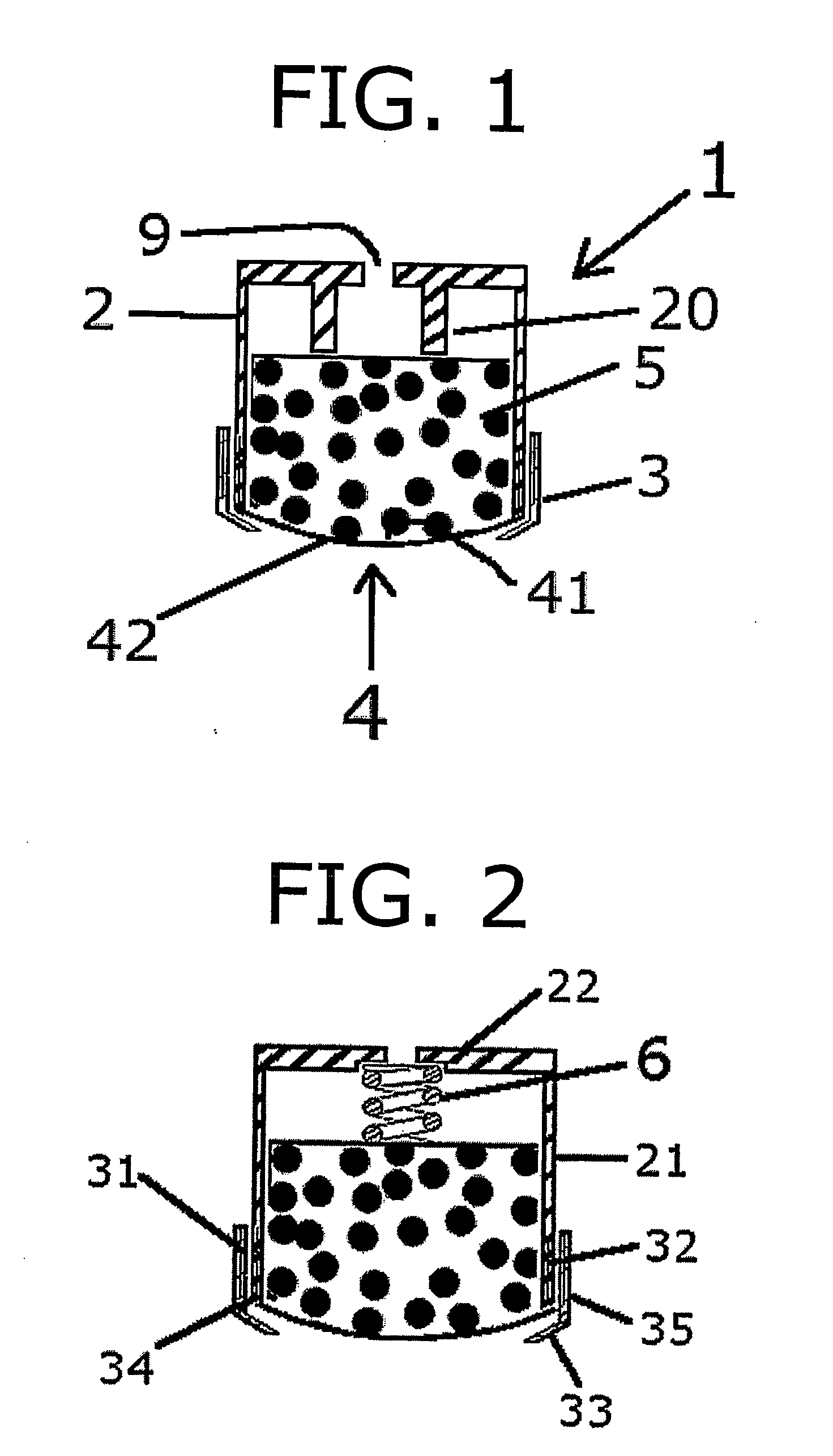
[0012]FIG. 1 shows a section through a single stamp head with a spacer element.

[0013]In FIG. 2 a sectional drawing is shown of a stamp head with a tampon pressing element.

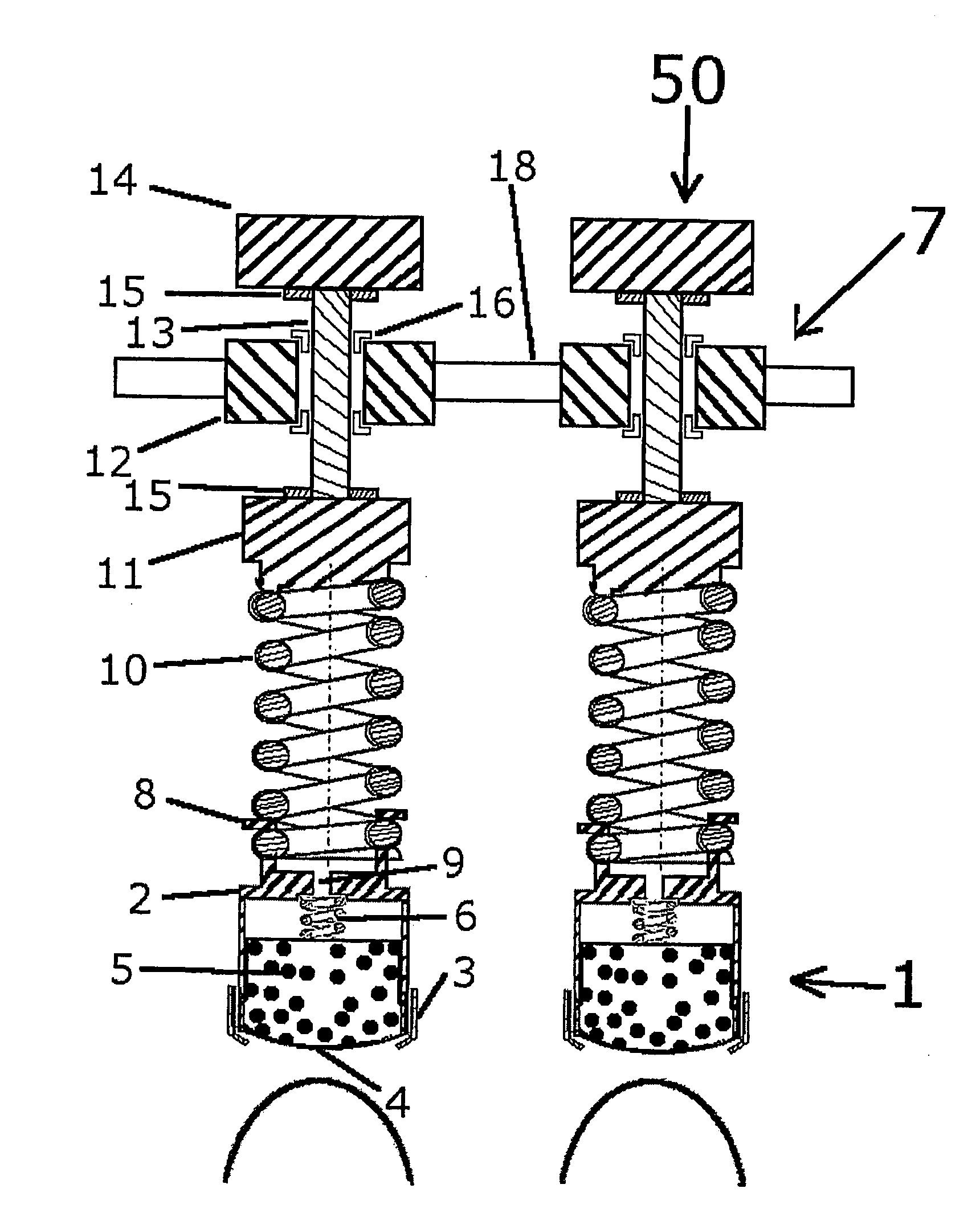
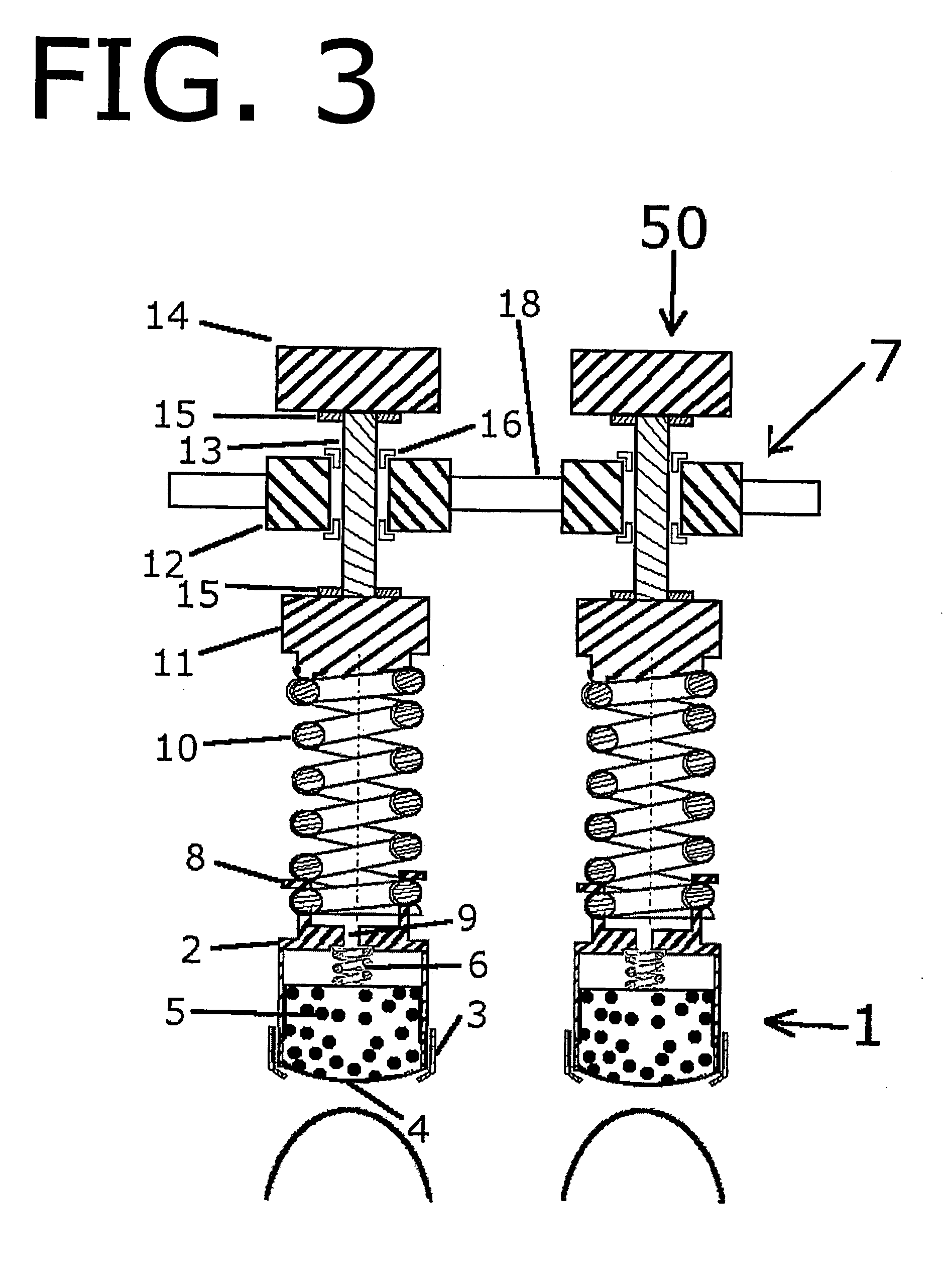
[0014]FIG. 3 shows a stamp device with two egg stamps which are fastened to a horizontal stamp bar.

[0015]In the attached drawing, a preferred example embodiment of the subject matter of the invention is illustrated and is explained by means of the following description.

DESCRIPTION

[0016]The multi-part stamp head 1 is constructed from a stamp head 2, in t...


PUM


Abstract

Disclosed is a stamp head (1) for printing uneven surfaces, especially agricultural products such as poultry eggs, by means of screen printing. The stamp ink is stored in a tampon (5) within a stamp chamber (2) and is transferred to the egg surface with the aid of structures of a small coated screen printing plate (4). The stamp head (2) can be fastened to a stamp guiding assembly (7) via a stamp pressing element (10) such that an egg stamp (50) is created which can be vertically moved up and down on a stamp bar (18), the stamping process being carried out by means of the vertical movement. Several egg stamps (50) can be mounted on the stamp bar (18) such that a stamping apparatus is created which allows several eggs to be printed simultaneously.

Description

TECHNICAL FIELD[0001]The present invention describes an apparatus for printing uneven surfaces, especially agricultural products such as poultry eggs, by screen printing by means of a stamp head in which a tampon with a stamp ink is housed and which is closed off by a small screen printing plate.PRIOR ART[0002]Printing apparatus for the printing of uneven surfaces and of poultry eggs have already been known for a long time.[0003]The egg stamper described in DE 70607 is constructed from a hollow cylinder which is closed off at one end by a stamp surface made of deformable material. This stamp surface is formed in a concave shape, projects into the volume of the hollow cylinder and has raised marks. A plunger is situated inside the hollow cylinder, the diameter of said plunger being selected so that it is movable in the hollow cylinder in a form-fitting manner. When the plunger is inserted into the hollow cylinder up to the stop, the plunger then presses onto the rear side of the stam...

Claims


Application Information

Patent Timeline
IPC IPC(8): B41F17/00
CPCA01K43/10B41K1/32B41F17/30B41F17/001
Inventor ISLER, WERNER
Owner NUOVO
Why Eureka
Try Eureka