
System and Method for Wireless Communications

Active Publication Date: 2009-10-08
FUTUREWEI TECH INC
View PDF8 Cites 61 Cited by
  • Summary
  • Abstract
  • Description
  • Claims
  • Application Information

AI Technical Summary

Benefits of technology

[0012]An advantage of an embodiment is that the performance improvements from beamforming may be achieved using one or a small number of antennas (along with a similarly small number of PAs and high-power signal cables). The small number of antennas may allow for the use of legacy communications towers with limited capability in the number of antennas that they are capable of supporting.
[0013]A further advantage of an embodiment is that the small number of antennas (as well as PAs and high-power signal cables) may significantly reduce the implementation costs of the wireless communications system in comparison to a comparable wireless communications system utilizing beamforming.
[0014]Yet another advantage of an embodiment is that existing hardware may be reused to further help reduce implementation costs.

Problems solved by technology

With each transmit and / or receive antenna, there is a number of electronic circuitry and components required to support the antenna, with a power amplifier (PA) used to amplify a signal to be transmitted and high-power signal cabling used to connect the PA to an antenna potentially being the most expensive.
The sheer physical size and weight of the high-power signal cabling may also present a problem with implementation.
However, since the communications tower may be leased to three or more service providers, each service provider may only have six (6) high-power signal cables on the communications tower.
This may restrict the service provider to having only two transmit / receive antennas per sector or one transmit and one receive antenna per sector, which may limit the service provider's ability to use beamforming.

Method used


Image

  • System and Method for Wireless Communications
  • System and Method for Wireless Communications
  • System and Method for Wireless Communications

Examples


Embodiment Construction

[0035]The making and using of the embodiments are discussed in detail below. It should be appreciated, however, that the present invention provides many applicable inventive concepts that can be embodied in a wide variety of specific contexts. The specific embodiments discussed are merely illustrative of specific ways to make and use the invention, and do not limit the scope of the invention.

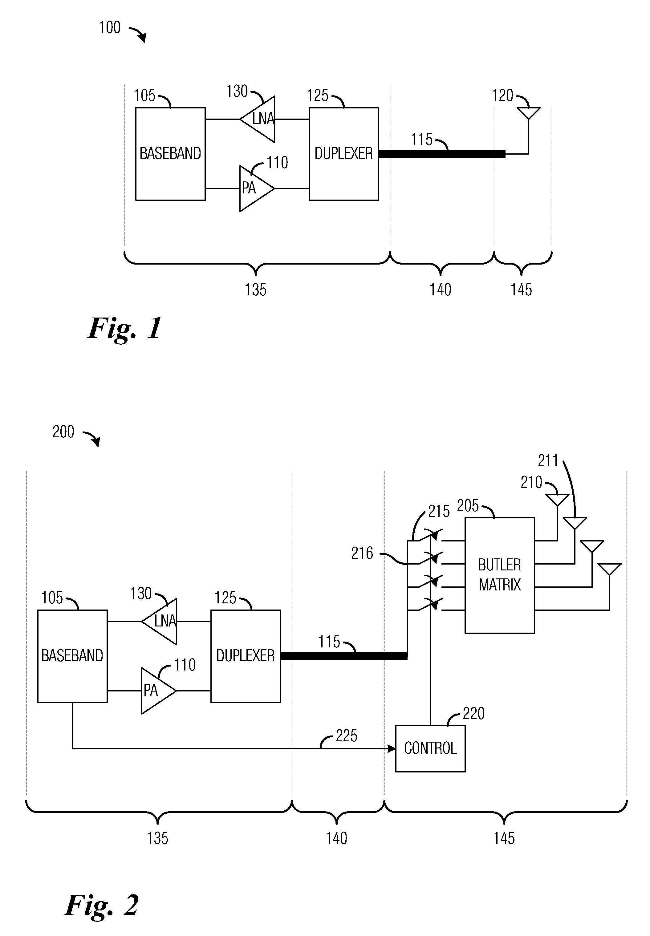
[0036]The embodiments will be described in a specific context, namely a time division duplex (TDD) or frequency division duplex (FDD) wireless communications system that uses a single PA and a single high-power signal cable to connect to four transmit antennas by way of a switching fabric. The invention may also be applied, however, to other TDD or FDD wireless communications systems with different numbers of transmit antennas, such as two, six, eight, and so forth. Furthermore, the wireless communications systems may make use of multiple high-power signal cables and PAs.

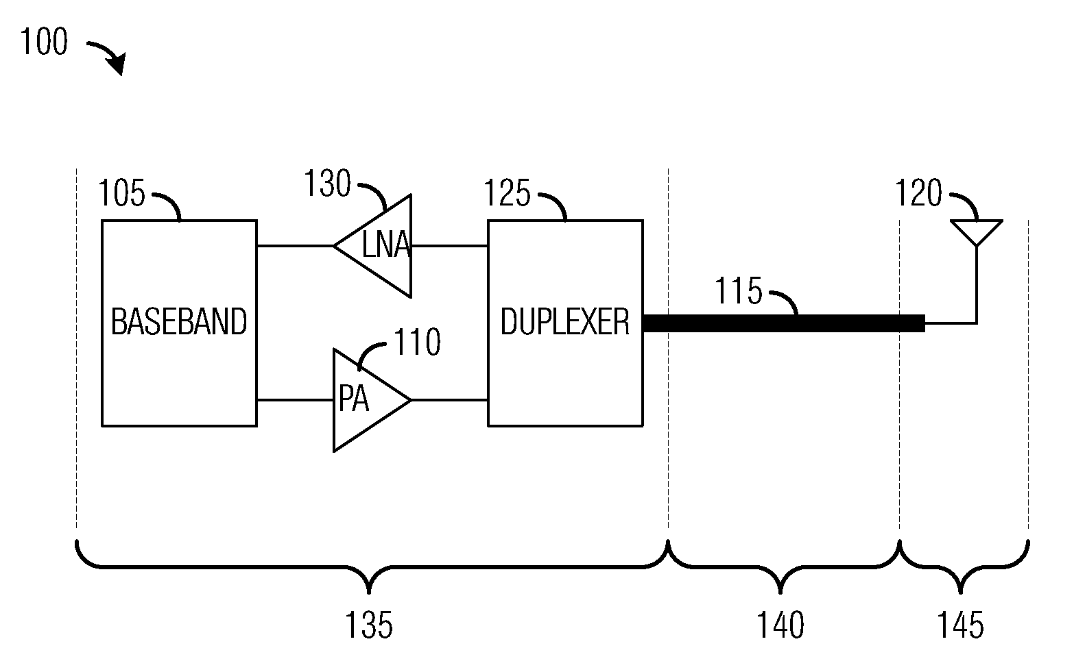
[0037]FIG. 1 is a diagra...


PUM


Abstract

A system and method for wirelessly communicating using beamswitching is provided. A communications system includes a high-power signal cable coupled to a signal amplifier, a radio frequency circuit coupled to the high-power signal cable, and a control unit coupled to the radio frequency circuit. The high-power signal cable conveys a transmission signal produced by the signal amplifier. The radio frequency circuit includes a plurality of antennas, a passive network having a plurality of output ports and a plurality of input ports, each output port coupled to an antenna of the plurality of antennas, and a plurality of switches coupled to the high-power signal cable, each switch coupled to an input port in the plurality of input ports. The control unit produces the control signal based on a specified coupling of the high-power signal cable to the passive network.

Description

[0001]This application claims the benefit of U.S. Provisional Application No. 61 / 042,682, filed on Apr. 4, 2008, entitled “One PA One Cable Beamswitcher,” which application is hereby incorporated herein by reference.TECHNICAL FIELD[0002]The present invention relates generally to wireless communications, and more particularly to a method and apparatus for wirelessly communicating using beamswitching.BACKGROUND[0003]In general, wireless communications systems using beamforming make use of a number of transmit and / or receive antennas and signal processing to create fixed or adaptive transmit / receive beampatterns. The beampatterns may have a directional nature that may result in a performance improvement when compared with unidirectional transmit and / or receive antennas. The use of the beampatterns may yield a transmit / receive gain over wireless communications systems using unidirectional transmit and / or receive antennas.[0004]In addition to increased computational requirements arising ...

Claims


Application Information

Patent Timeline
IPC IPC(8): H04B1/38
CPCH01Q3/40H01Q25/00H04B7/0602H04B7/0632H04W88/08H04B7/0695H04B7/10H04W16/28H04B7/0669
Inventor VAN RENSBURG, CORNELIUSSANAYEI, SHAHABKWON, YOUNG HOONSOONG, ANTHONY C.K.
Owner FUTUREWEI TECH INC
Learn More