Flotation Method

a technology of flotation and impeller speed, which is applied in the direction of flotation, solid separation, chemistry apparatus and processes, etc., can solve the problems of further air entrainment, inability to adjust the impeller speed in order to affect one of its functions,

Inactive Publication Date: 2009-10-08
XSTRATA TECH PTY LTD
View PDF2 Cites 16 Cited by
  • Summary
  • Abstract
  • Description
  • Claims
  • Application Information

AI Technical Summary

Benefits of technology

[0040]Suitably, the jet created by the slurry passing through the slurry lens promotes the inducement of air into the downcomer and the shearing action of the jet generates fine bubbles and transports them through the mixing zone. Particles and the bubbles collide and attach to each other and subsequently travel down the downcomer through the pipe flow zone where bubbles are removed by hydrostatic pressure from the downcomer creating a vacuum for further air entrainment

Problems solved by technology

Consequently, it is not possible to adjust impeller speed in order to affect one of its functions (such as particle suspension) without affecting the other functions (such as bubble creation and bubble / particle collision / attachment).
Additionally, the periodic collapse of the induction trumpet results in further air entrainment.

Method used


Image

  • Flotation Method
  • Flotation Method
  • Flotation Method

Examples


examples

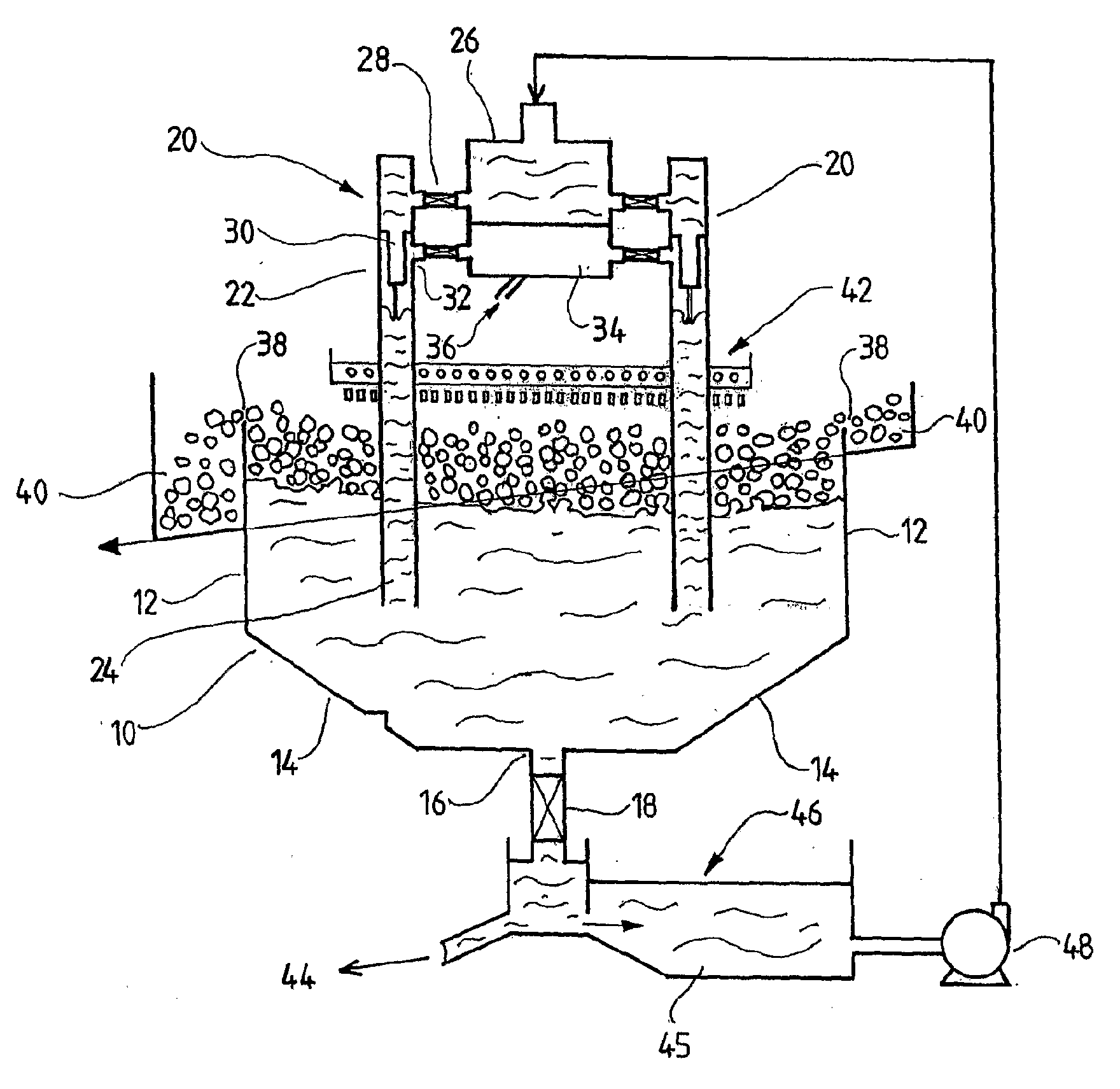
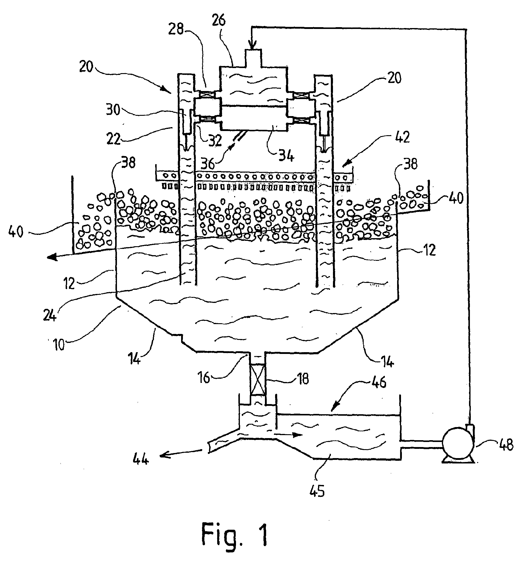
[0064]The present invention was tested on coal through a pilot plant Jameson Cell located in the Bowen Basin of Queensland. The Jameson Cell had an industrial sized downcomer, 280 mm in diameter, situated in a cell 1.6 m in diameter. A bleed off stream from the processing plant fed the Jameson Cell. The pilot cell had a variable speed pump, as well as several different sized slurry lenses, which permitted different jet velocities in the downcomer to be tested. A valve and flowmeter was connected to the air inlet, that permitted varying the air to pulp ratio. The air to pulp ratio, or APR, is the measure of the volumetric flowrate of air that is mixed with the volumetric flowrate of slurry. Hence an APR of 1 implies there is an equal volume of air mixed with an equal volume of slurry. Industrial sized Jameson Cells have an APR ranging from 0.7 to 1.5, although this testwork confirmed that an APR of 1.7 can be successfully used in a Jameson Cell.

[0065]In the testwork, it was highlight...


PUM


Abstract

A flotation method in which a liquid or slurry is fed to a downcomer (20) where it forms a region of high void fraction which moves out of the downcomer (20) into a vessel (10) in which a froth rises and liquid or slurry falls, characterized in that the liquid or slurry is fed to the downcomer (20) with a jet velocity as it exits an orifice and enters a free jet zone of less than 8 metres / second.

Description

FIELD OF THE INVENTION[0001]The present invention relates to a flotation method.BACKGROUND TO THE INVENTION[0002]Flotation is a well known technique for separating particulate material from slurry suspensions. In flotation, the slurry containing the particles is treated with reagents to render certain particles hydrophobic (water repellent) and a gas, typically air, is emitted into the suspension in the form of small bubbles. When the hydrophobic particles come into contact with the bubbles, the hydrophobic particles adhere to the bubbles. Due to hydrostatic forces, the bubbles, together with adherent particles, rise upwardly through the slurry to form a froth. The froth containing the adherent particles is then removed as a concentrate or product, whilst any hydrophilic (water loving) particles are left behind in the slurry phase and flow out with the slurry phase as tailings. Flotation processes can be applied to suspensions of minerals in water, suspensions of coal in water, to t...

Claims


Application Information

Patent Timeline
Patent Type & Authority Applications(United States)
IPC IPC(8): B03D1/24
CPCB03D1/24B03D1/247B03D1/082B03D1/028B03D1/1468
Inventor YOUNG, MICHAEL FRANCISGIRARD, STEPHANECOWBURN, JOAN ANN
Owner XSTRATA TECH PTY LTD
Why Eureka
Try Eureka