
Packing material fitting structure

a technology of fitting structure and fitting material, which is applied in the direction of engine sealing, machine/engine sealing arrangement, etc., can solve the problems of difficult to verify whether the projection has been reliably and accurately inserted into the cutout portion, and achieve the effect of improving the quality of assembling the packing with the casing, easy to view, and stable fitting sta

Inactive Publication Date: 2009-10-01
YAMADA SEISAKUSHO KK
View PDF11 Cites 5 Cited by
  • Summary
  • Abstract
  • Description
  • Claims
  • Application Information

AI Technical Summary

Benefits of technology

"The present invention provides a packing material fitting structure for a casing that can securely and easily mount a packing material on a fitting groove in the casing. The structure includes a packing material with protruding portions that are inserted into the fitting groove and fixed by a cutout portion in the groove. The protruding portions have an auxiliary protruding portion that is pressed and fixed by the cutout portion. This makes it difficult for the packing material to separate from the casing during transportation. The invention also provides a method for easily inserting and disposing the packing material in the fitting groove. The structure and method ensure that the packing material is securely mounted on the casing and can withstand impact during transportation."

Problems solved by technology

Furthermore, it is difficult to verify whether the projection has been reliably and accurately inserted into the cutout portion.

Method used


Image

  • Packing material fitting structure
  • Packing material fitting structure
  • Packing material fitting structure

Examples


Embodiment Construction

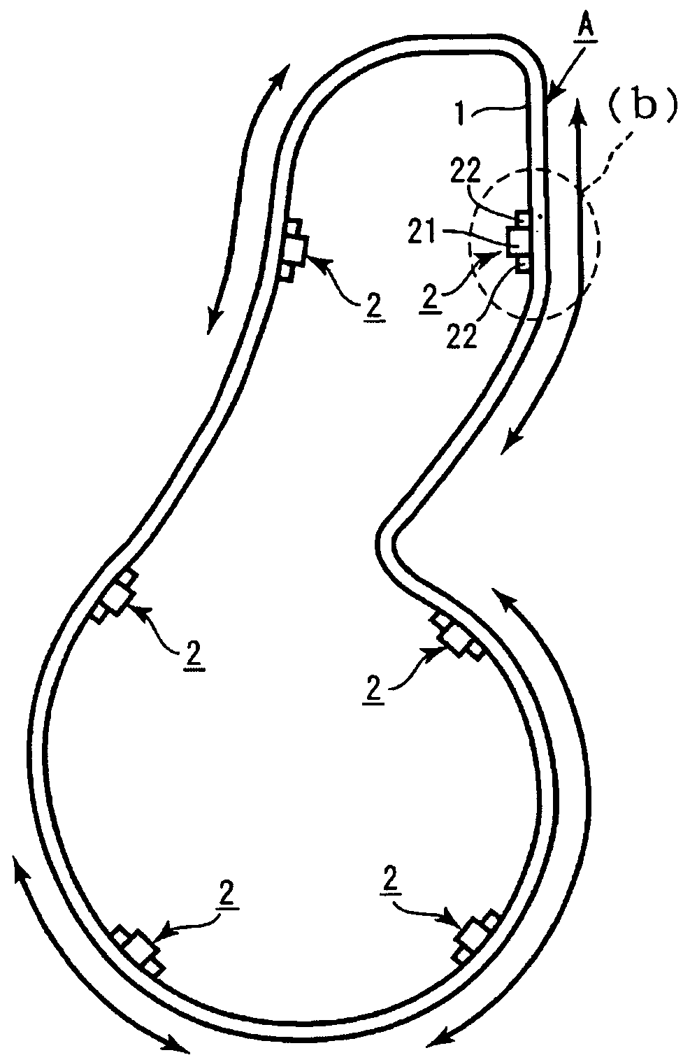
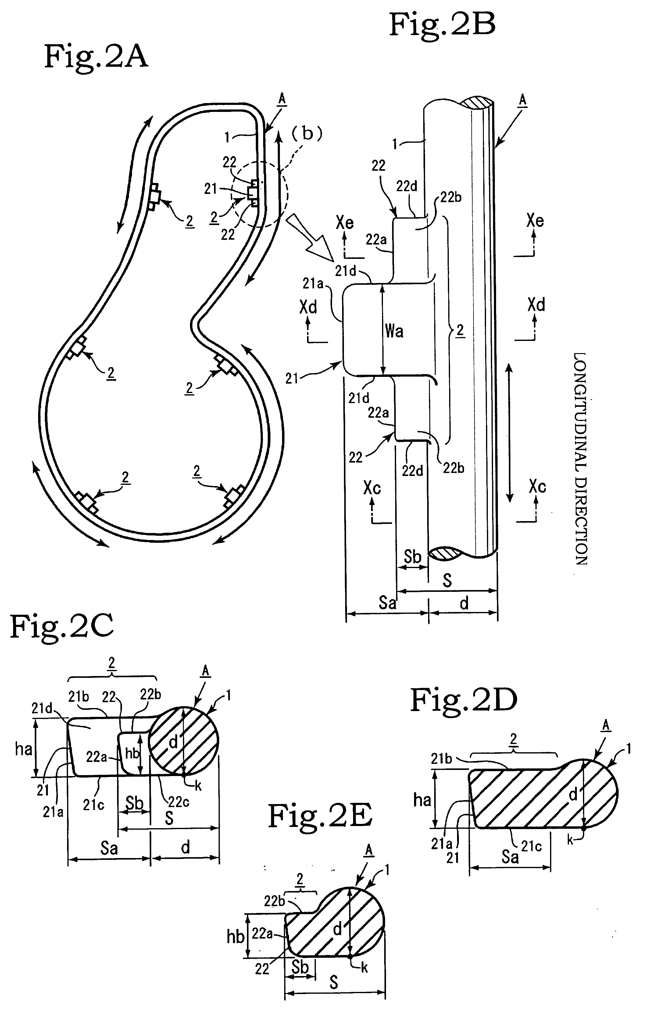
[0025]An embodiment of the present invention will be described below with reference to the appended drawings. As shown in FIG. 1 and FIG. 2, a packing material A is composed of an annular main body portion 1 and a plurality of projections 2, 2, . . . . The plurality of projections 2, 2, . . . are formed with an appropriate spacing along the longitudinal direction of the annular main body portion 1. The longitudinal direction of the annular main body portion 1 is the same direction as the circumferential direction of the annular main body portion 1. The longitudinal direction of the annular main body portion 1 is along the circumference of the annular main body portion 1 (see FIG. 2A). As shown in FIG. 2A, the annular main body portion 1 has an endless annular (loop) shape and is formed to have a shape substantially identical to the shape in the longitudinal direction of a fitting groove 4 of the below-described casing B. The annular main body portion has a definite shape such as a r...


PUM


Abstract

A packing material fitting structure that prevents the packing material from easily dropping out and facilitates mounting and fixing of the packing material in a packing material fitting place in a part such as a casing or a cover of an engine or a pump with sealing ability. The fitting structure is provided with a packing material having an annular main body portion and a plurality of projections each having a main protruding portion formed to protrude from the annular main body portion and an auxiliary protruding portion formed integrally in the vicinity of the main protruding portion, the projections being formed with an appropriate spacing in the longitudinal direction of the main annular main body portion. The fitting structure is also provided with a casing having formed therein an annular fitting groove for inserting the annular main body portion of the packing material. A cutout portion into which only the main protruding portion of the projection is inserted is formed in a groove wall portion of the fitting groove. An integral forming region of the auxiliary protruding portion and the annular main body portion has a width substantially equal to or larger than a width of the fitting groove. In the packing material, a projection formation location is pressed and fixed only by the cutout portion and both groove wall portions in the vicinity of the cutout portion.

Description

BACKGROUND OF THE INVENTION[0001]1. Field of the Invention[0002]The present invention relates to a packing material fitting structure such that the packing material can be prevented from easily separating or dropping out of a fitting groove in a packing material fitting place in a part such as a casing or a cover of an engine or a pump with sealing property, the packing material can be easily mounted and fixed, and the sealing ability in the packing material fixing place can be prevented from decreasing.[0003]2. Description of the Related Art[0004]Packing materials have been widely used in portions requiring sealing ability in parts such as casings and covers of engines, pumps, and the like. An annular (loop-shaped) groove is formed in a joining surface to mount the packing material between the joining surfaces of structural members such as casings and covers, and a packing material of a similar annular shape is mounted along the longitudinal direction of the fitting groove. In most...

Claims


Application Information

Patent Timeline
Patent Type & Authority Applications(United States)
IPC IPC(8): F02F11/00
CPCF16J15/061F16J15/106F16J15/062
Inventor YOSHIDA, HARUYOSHI
Owner YAMADA SEISAKUSHO KK
Learn More