Downhole Tubular Expansion Tool and Method

a tubular and well technology, applied in the direction of drilling casings, drilling pipes, borehole/well accessories, etc., can solve the problems of unsafe condition, difficult and expensive to (a) retrieve the tool to the surface to repair the tool, and achieve the effect of moving through the upper end reliably

Active Publication Date: 2009-10-01
TIW
View PDF12 Cites 54 Cited by
  • Summary
  • Abstract
  • Description
  • Claims
  • Application Information

AI Technical Summary

Benefits of technology

[0009]In another embodiment, the tool includes a slip assembly positioned above the tubular expander for securing the tool to a downhole tubular. The tool may be picked up at the surface through the work string to release the slips after an expansion stroke. In a preferred embodiment, the downhole actuator includes a hydraulically powered drive assembly for separately setting the slips and later moving the expander axially within the downhole tubular. Improvements allow the expander to reliably move through the upper end of the tubular being expanded, since slips secure the tool axially within the well during this final expansion.

Problems solved by technology

One of the problems with prior art expansion tools is that the tubular expander itself is frequently housed within an outer tubular housing which inherently has a diameter greater than the diameter of the expander.
Accordingly, it is frequently difficult to position this housing with the internal expander therein at the desired location at the lower end of the tubular in a well, particularly when there is a substantial variance between the OD of the tubular expander housing and the OD of the tubular prior to being expanded.
A further significant problem with conventional tubular expander techniques is that axial movement of the tubular expander must be stopped before reaching the upper end of the tubular being expanded, since an expander under high force will tend to “shoot past” the upper end of the tubular during the expansion process, thereby resulting in an unsafe condition.
While some of these tools have met with success, a significant disadvantage to these tools is that, if a tool is unable to continue its expansion operation (whether due to the characteristics of a hard formation about the tubular, failure of one or more tool components, or otherwise), it is difficult and expensive to (a) retrieve the tool to the surface to repair the tool, (b) utilize a more powerful tool from the beginning to continue the downhole tubular expansion operation, or (c) sidetrack around the stuck expander.

Method used


Image

  • Downhole Tubular Expansion Tool and Method
  • Downhole Tubular Expansion Tool and Method
  • Downhole Tubular Expansion Tool and Method

Examples


Embodiment Construction

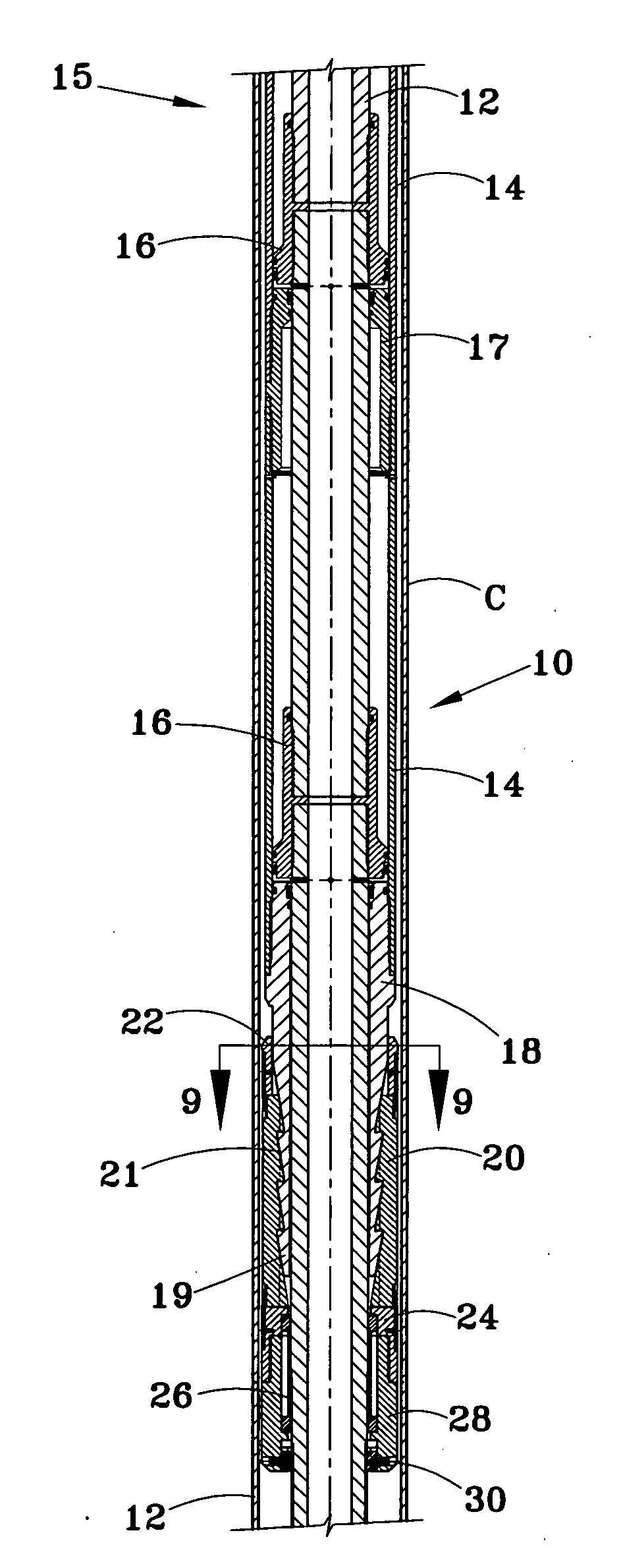
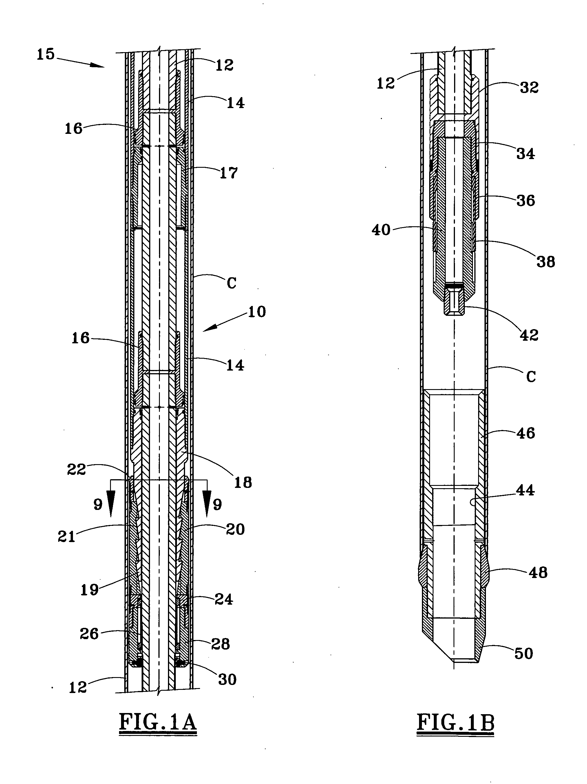
[0031]FIG. 1 illustrates one embodiment of a expansion tool 10 which may be used to expand a liner, casing, or other tubular C within a well. FIG. 1, as well as other figures discussed below, illustrates upper, lower, or intermediate portions of an axially elongate tool. The tubular C and the tool may be run and the tubular expanded in an uncased portion of a well, or may be run in a cased portion of a well. A particular feature of the invention is the use a downhole actuator 15, which may be hydraulically powered, to expand one or more relatively short portions of the tubular C. Thereafter, the secured engagement of the expanded portion of the tubular with the well (either an outer casing or the borehole wall) allows an axial pull on the work string which run the tool in the well to pull up on the tool and thus upon the expander to thereby expand a relatively long portion of the tubular C.

[0032]FIGS. 1A and 1B illustrates a representative portion of a drill pipe or other work strin...


PUM


Abstract

A tool 10 is provided for radially expanding a downhole tubular C, and includes a central tool mandrel 12 which functionally is part of a drill string or work string, a tubular expander 48 at the lower end of the tubular, and a downhole actuator 15 for forcibly moving the expander axially within the downhole tubular. Slips 20 are positioned for securing the tool within the tubular, so that the slips may be set, and the tool subsequently stroked to move the expander 48 and radially expand a length of the tubular. Upward pull on the work string may expand long portions of the downhole tubular.

Description

CROSS REFERENCE TO RELATED APPLICATION[0001]This application is a continuation-in-part of U.S. patent application Ser. No. 11 / 803,389 filed on May 12, 2007, and claims priority from the parent application.FIELD OF THE INVENTION[0002]The present invention relates to tools and techniques for expanding a tubular in a well. More particularly, the invention relates to a highly reliable tubular expansion tool which may be positioned downhole and hydraulically stroked to expand a relatively short length of the downhole tubular or pulled upward from the surface to expand a long length of the downhole tubular.BACKGROUND OF THE INVENTION[0003]One of the problems with prior art expansion tools is that the tubular expander itself is frequently housed within an outer tubular housing which inherently has a diameter greater than the diameter of the expander. Accordingly, it is frequently difficult to position this housing with the internal expander therein at the desired location at the lower end ...

Claims


Application Information

Patent Timeline
Patent Type & Authority Applications(United States)
IPC IPC(8): E21B29/00E21B43/10E21B29/10
CPCE21B43/105E21B7/20E21B43/103
Inventor BRADDICK, BRITT O.
Owner TIW
Why Eureka
Try Eureka