Substructure and crawl space enclosure for factory constructed buildings

a technology for factory buildings and crawl spaces, applied in constructions, building repairs, building material handling, etc., can solve the problems of not supporting the structure, not addressing the transfer of forces to the ground, and current building codes will not allow construction in such conditions. to achieve the effect of facilitating installation

Inactive Publication Date: 2009-10-01
LILIEN ARTHUR +1
View PDF7 Cites 8 Cited by
  • Summary
  • Abstract
  • Description
  • Claims
  • Application Information

AI Technical Summary

Benefits of technology

[0003]The invention requires the installation of a ground interface or “foundation”, such as a continuous reinforced concrete grade beam which is either cast in-situ or pre-cast, or isolated concrete footings, either cast in-situ or pre-cast, or a treated wood foundation in a gravel bed. Said ground interface is engineered to transmit gravity, wind, snow, and seismic forces to the earth and below frost level if necessary. Said ground interface is laid so that the top surface is level with the surrounding grade. If the building modules are to be set in a pit, with the crawl space below grade, then a ramp must be graded to facilitate installation. Said building modules can then be maneuvered via truck close to their final location on the temporary running gear used for overland transportation to the site. Said temporary running gear is installed at the factory where said building modules are built. Said building modules can be maneuvered into their exact locations over said ground interface using commercially available rollers and jacks. This process is not dangerous as said modules still possess their wheels and hitch's or carriers, which prevent falling. A plurality of support stanchions, one of the components of the invention, are then positioned and attached to the perimeter structural members of said building modules using nut and bolt fasteners. Said stanchions are attached to said ground interface with anchoring bolts. Said building modules are then lifted off said wheels and hitches or carriers by said stanchion's adjustable screw. Said temporary wheels and axles or carrier can then be safely removed. Said stanchions allow for fine leveling, to 1 / 16th of an inch. Said building's utilities can be easily connected to the underside of said building modules as the perimeter of said crawl space is wide open. The pre-cast cementitous panels, which are a component of the invention, are then attached to said stanchions via commercially available panel adhesive and screw fasteners. Said metal stanchions and said pre-cast cementitious panels once attached together constitute the complete invention and became a single structural entity with greater capacity to transmit gravity, wind, snow and seismic forces to said ground interface than the components can independently. Said invention is labor saving, adjustable, and extremely strong. Said invention also allows for future re-leveling in the event of differential settlement. Ventilation for said crawl space is accomplished by a screened gap between said pre-cast cementitious panel and the underside of said building modules. Said gap may be hidden by said building's stucco screed or exterior sheathing. Said pre-cast cementitious panels can be backfilled with earth so that the floor level inside said building can be closer to the outside grade.

Problems solved by technology

Research yielded many inventions which used panelized systems designed to enclose the crawl spaces of manufactured buildings and retain soil when backfilled, but do not support the structure.
The Lear patent addresses ease of construction and the ability to re-level a structure after soil heaving or failure but does not address transferring any forces to the ground.
Current building codes will not allow for construction in such conditions.
It will not support the structure or allow backfilling to grade.
The lack of lateral strength will cause the system to be deficient in carrying wind and seismic forces to the ground interface.
The system requires potentially hazardous and time consuming pre-leveling on temporary blocking.
The patent does not teach a soil retaining system for the crawl space in below ground installations.
The Butler system requires hazardous pre-leveling on temporary blocking.
The corrugated sheets are in close proximity to the earth and even with a coating can be subject to corrosion when backfilled.
Although the Butler invention possesses the strength necessary to transfer gravity, snow, wind and seismic loads to the ground, as required by current building codes, it is very labor intensive to install in comparison to the currently disclosed invention and is potentially subject to corrosion when backfilled.

Method used


Image

  • Substructure and crawl space enclosure for factory constructed buildings
  • Substructure and crawl space enclosure for factory constructed buildings
  • Substructure and crawl space enclosure for factory constructed buildings

Examples


Embodiment Construction

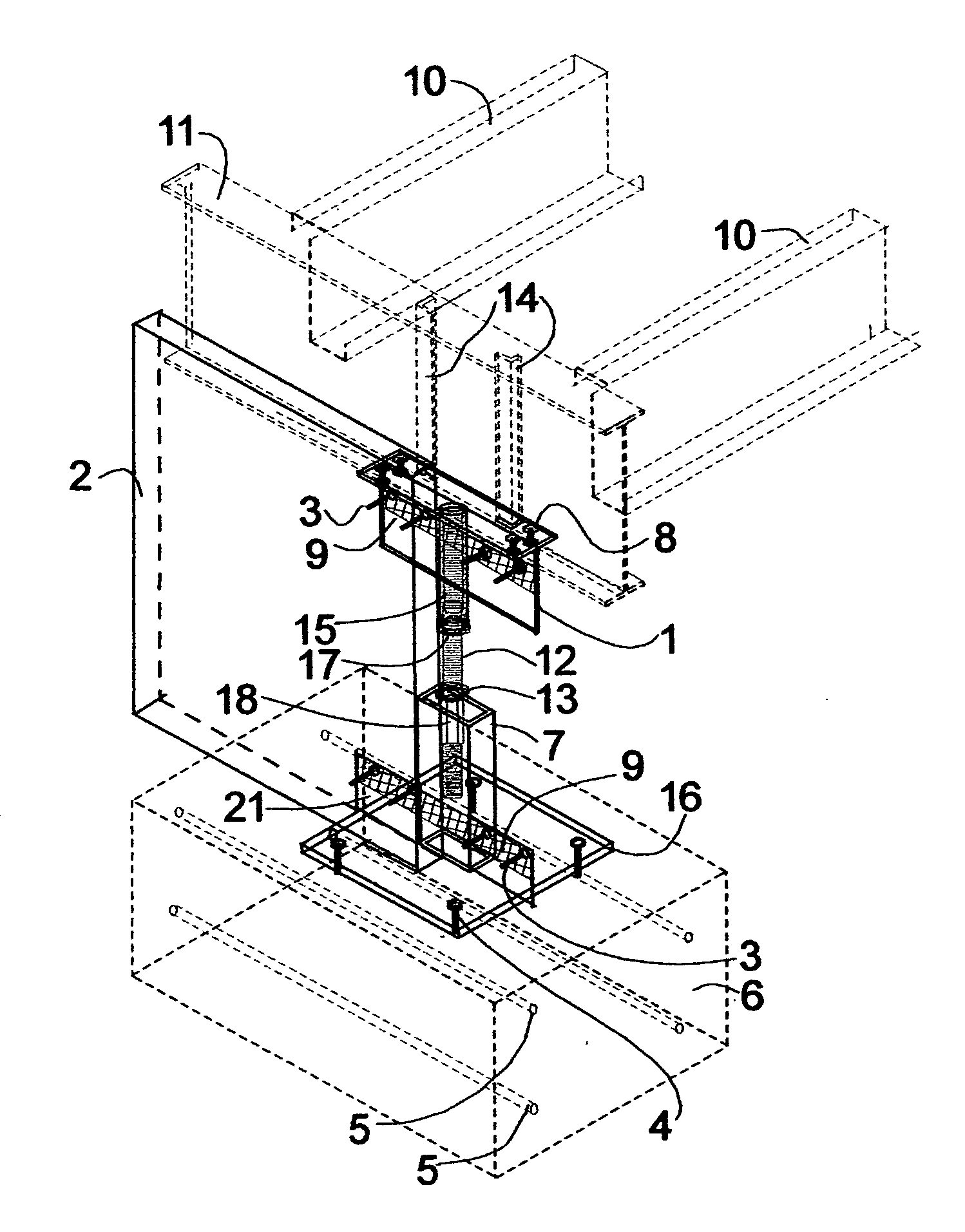
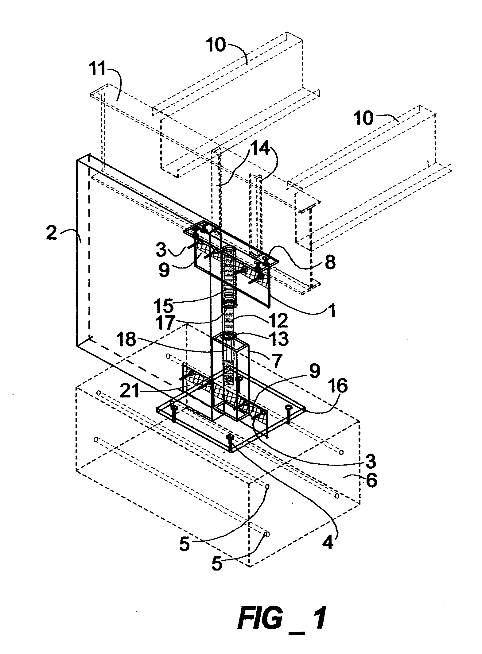
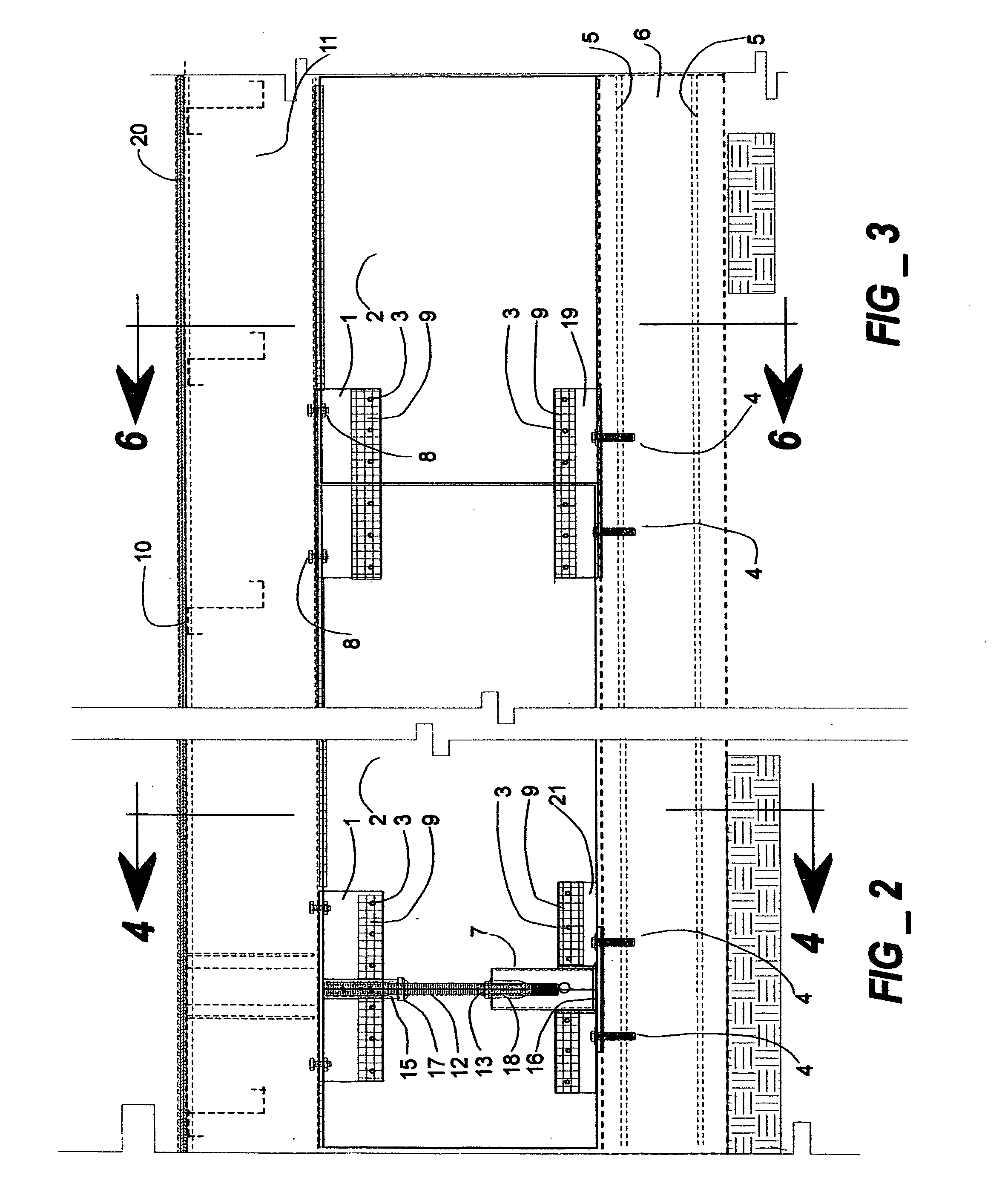
[0016]There are four main components that constitute the substructure and crawl space enclosure for factory constructed buildings. Two of said main components of the preferred embodiment of the invention are located in FIGS. 1, 2, and 4, between 6 and 11. The first main component 2 is a pre-cast cementitious panel. The second main component is a fabricated metal stanchion assembly composed of 1, 7, 12, 13, 15, 16, 17, 18 and 21. The third main component, a splicing assembly, FIGS. 3, 6 and 7, which is composed of structural metal “T”1 and metal angle 19 used to structurally connect pre-cast cementitious panels 2 together where a fabricated metal stanchion is not needed. The fourth main component is a fabricated metal stanchion assembly, FIGS. 8 and 11, composed of 1, 7, 12, 13, 15, 16, 17, and 18. Said stanchion is used between factory constructed building modules for support where pre-cast cementatous panels 2 are not needed.

[0017]Item 6 is the ground interface to which said invent...


PUM


Abstract

A building support system assembled on a ground interface such as, but not limited to, an in-situ poured continuous concrete grade beam, using a plurality of adjustable stanchions and pre-cast cementitious panels. The fabricated stanchions attach to the building perimeter structural element and to said ground interface. Pre-cast cementitious panels with shear capacity attach to the stanchions, enclose the crawl space, retain soil, provide weather protection and with all components acting together transfer gravity, wind, snow and seismic forces from said building to said ground interface. The system has provisions for crawl space ventilation.

Description

REFERENCES CITED [0001]U.S. PATENT DOCUMENTS3,831,3298 / 1974Lear52 / 1264,458,4637 / 1984Behrend52 / 2954,680,9047 / 1987Stoeker52 / 169.124,738,0614 / 1988Herndon52 / 126.65,664,3779 / 1997Angelo and Kambozia52 / 2956,076,3206 / 2000Butler52 / 294BACKGROUND OF THE INVENTION[0002]The purpose of the invention is to facilitate a new and improved apparatus and method for installing factory constructed buildings that require perimeter support. These structures include factory built housing, commercial modular buildings and some manufactured homes. Conventionally said buildings are set on masonry block or stem wall foundations, which are often faulty dimensionally and out of level. These faults result in unsatisfactory results such as out of level floors, out of plumb walls, doors, and windows. Installation is often hazardous using either costly cranes or labor intensive sliding, adjusting and attaching. Utility connections are made working through tiny / access doors and working around internal walls with limit...

Claims


Application Information

Patent Timeline
IPC IPC(8): E02D27/32
CPCE02D27/01
Inventor LILIEN, ARTHURLILIEN, DUANE S.
Owner LILIEN ARTHUR
Why Eureka
Try Eureka