
Ld module

Inactive Publication Date: 2009-09-24
NEC CORP
View PDF3 Cites 3 Cited by
  • Summary
  • Abstract
  • Description
  • Claims
  • Application Information

AI Technical Summary

Benefits of technology

[0015]The present invention was made in view of the above circumstances and has an exemplary object to provide an LD module that can detect a wavelength fluctuation with a simple configuration and can reduce its size and prices.

Problems solved by technology

(1) The number of components becomes larger than that of a usual LD module;
(2) The larger number of components makes size reduction difficult and in addition, a need to add a large number of expensive optical components such as a beam splitter 23 and a wavelength filter 24 unavoidably raises the price of the product as a whole; and
(3) Since the beam splitter 23 and the wavelength filter 24 are required to be arranged extremely precisely, drastic increase in time required for manufacture and occurrence of yield are unavoidable.
Also, with the configuration of the related art shown in FIG. 5, since expensive optical components such as the beam splitter 23 and the wavelength filter 24 need to be used, there is a problem that a product price is raised.

Method used


Image

  • Ld module
  • Ld module
  • Ld module

Examples


exemplary embodiment 1

[0032]An exemplary embodiment of an LD module according to the present invention will be described below.

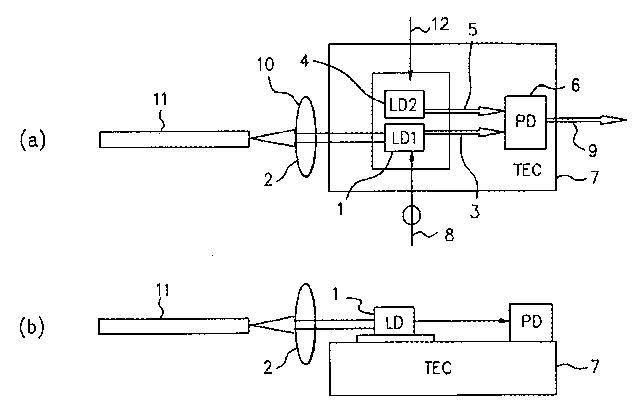
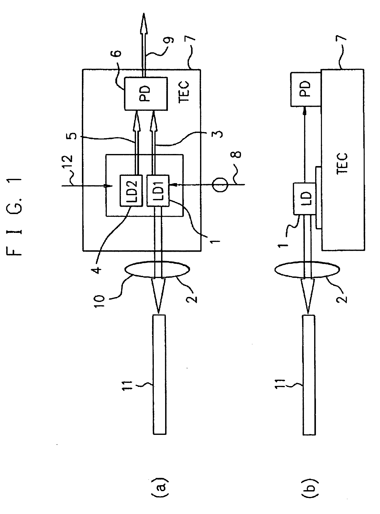
[0033]FIG. 1A is a top view illustrating an exemplary embodiment of the LD module according to the present invention and FIG. 1B is a side view of FIG. 1A.

[0034]On an electronic temperature control element (Peltier element, also called thermo electrical cooling module (TEC)) 7 whose surface temperature is changed by a current amount flowing therethrough, an LD element 1 for modulation as a double-sided light-emitting LD element converting a modulation (electric) signal 8 to an optical signal 2, a reference LD element 4 whose temperature dependence of an oscillation wavelength is different from that of the LD element 1 for modulation, and a PD element 6 for receiving a backward light 3 of the LD element 1 for modulation and an output light 5 of the reference LD element 4 and converting them to an electric current 9 are mounted.

[0035]The components mounted on the electronic tempera...

exemplary embodiment 2

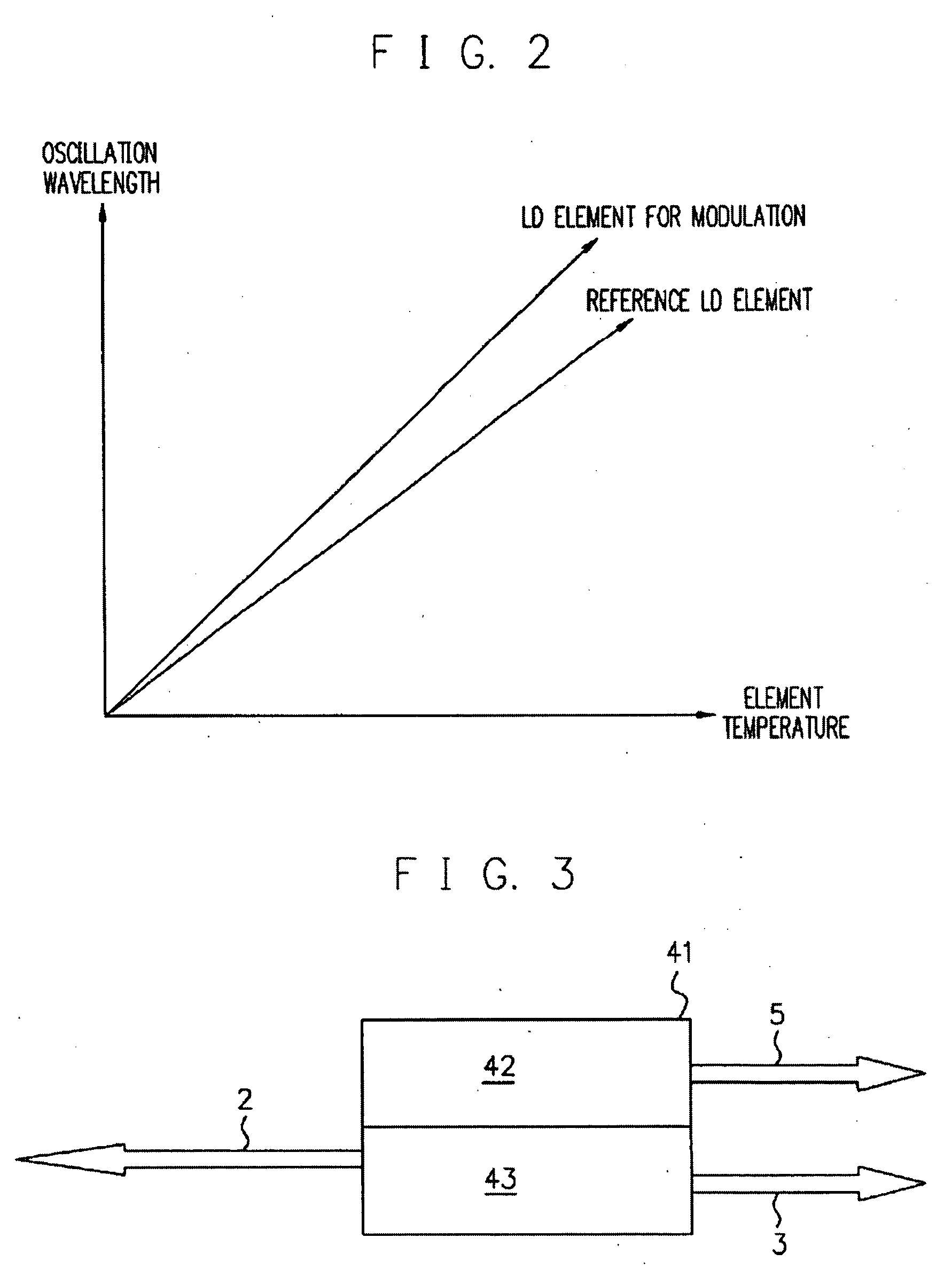
[0052]FIG. 3 is a plan view illustrating another exemplary embodiment of the LD module according to the present invention.

[0053]As shown in FIG. 3, with regard to the LD for modulation and the LD for reference, the LD element 1 for modulation and the LD element 4 for reference can be formed in the lump on a single chip in an LD element manufacturing process (this method can be considered the most ideal). FIG. 3 shows that an LD portion 43 for modulation and a reference LD portion 42 are formed on a single chip 41.

exemplary embodiment 3

[0054]FIG. 4 is a plan view illustrating another exemplary embodiment of the LD module according to the present invention.

[0055]As shown in FIG. 4, even if the LD element for modulation is changed to an integrated LD element of external modulator, configuration is possible without a problem. FIG. 4 shows that a reference LD portion 52 and an integrated LD 53 of external modulator (modulator portion 55, CW-LD portion 54) are formed on a single chip 51.


PUM


Abstract

The present invention is to provide an LD module that can detect a wavelength fluctuation with a simple configuration and can reduce its size and prices. The LD module includes a double-sided light-emitting LD element for emitting an output light and a backward light in both forward and backward directions, a reference LD element whose temperature dependence of an oscillation wavelength is different from that of the double-sided light-emitting LD element, and a PD for receiving a multiplexed wave of the backward light of the double-sided light-emitting LD element and an output light of the reference LD element and detecting a beat component generated by the multiplexing.

Description

[0001]This application is based upon and claims the benefit of priority from Japanese patent application No. 2008-071163, filed on Mar. 19, 2008, the disclosure of which is incorporated herein in its entirety by reference.BACKGROUND ART[0002]1. Technical Field[0003]The present invention relates to an LD module.[0004]2. Description of Related Art[0005]FIG. 5 is a plan view of an LD module relating to the present invention.[0006]In the LD (Laser Diode) module shown in the figure, a backward light 3 from an LD element 1 for modulation is split by a beam splitter 23 to two lights 25 and 26, one light 25 of which is received by a PD (Photo Diode) 21 as it is, while the other light 26 passes through a wavelength filter 24 and then, is received by a PD 22, and by comparing light-receiving currents 28 and 29 outputted from each of the PDs 21 and 22, a change in the wavelength is detected.[0007]An example of such a technology is described in Patent Document 1 (Japanese Patent Laid Open Publi...

Claims


Application Information

Patent Timeline
IPC IPC(8): H01S5/026
CPCH01S5/02248H01S5/0687H01S5/06804H01S5/02284H01S5/02251H01S5/02325
Inventor YAMANE, TAKASHI
Owner NEC CORP
Learn More