
Tongue depressor

Inactive Publication Date: 2009-09-17
BHATT SAMIR
View PDF6 Cites 7 Cited by
  • Summary
  • Abstract
  • Description
  • Claims
  • Application Information

AI Technical Summary

Benefits of technology

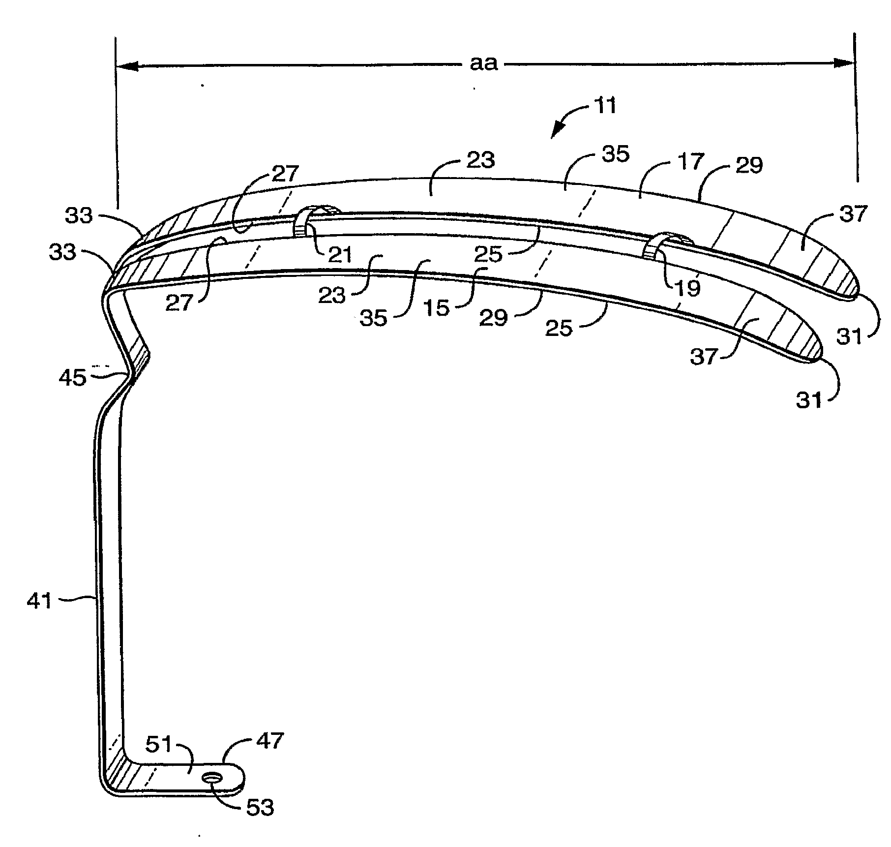
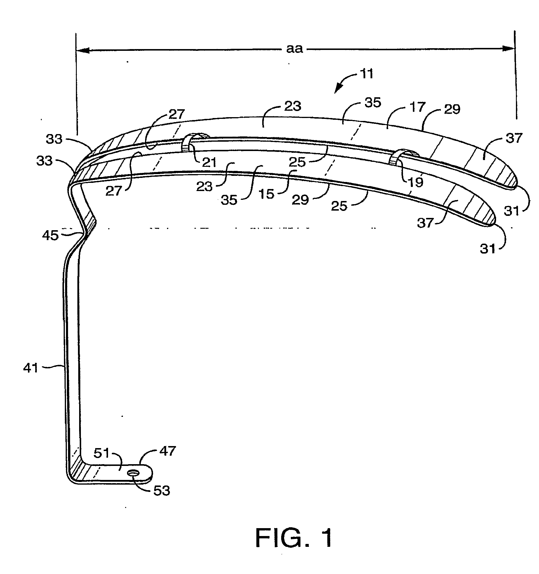
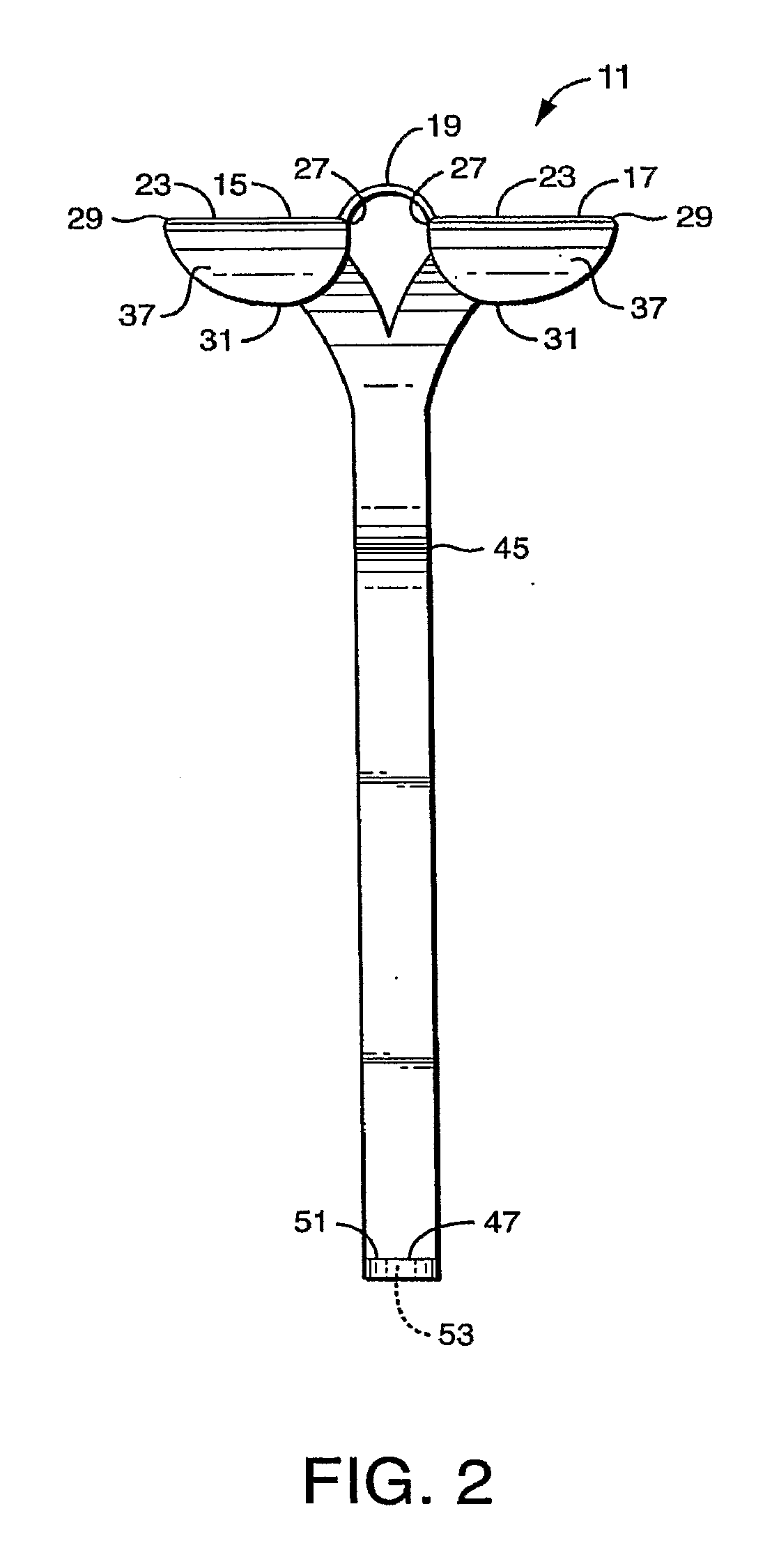
[0008]The open channel space allows the surgeon to view the ventilation means during use of the device. During insertion and removal, the surgeon may view the ventilation means to insure that the ventilation means is properly positioned. The surgeon can also manually move or position the ventilation means to accommodate the needs of the surgical procedure. The one or more bridge elements allow the surgeon to have substantial view of the surgical field.
[0017]The fitting of the device is facilitated with a handle extending from at least one of the first and second planar elements. In one embodiment, the device may be stored conveniently with a hanging means to be available to a surgeon for next use.

Problems solved by technology

Neither the Davis nor the Doughty varieties fits well with laryngeal mask airways (LMAs) being used for general anesthesia during tonsillectomy procedures, causing problems with surgical access and safe patient ventilation.
The present mouth gags are associated with several problems.
During insertion, these devices rub against LMA breathing tubes in a way that coils, kinks or displaces the LMA, causing difficult or inadequate patient ventilation.
During removal, these mouth gags trap the breathing tubes in their grooves making accidental removal a dangerous possibility.

Method used


Image

  • Tongue depressor
  • Tongue depressor
  • Tongue depressor

Examples


Embodiment Construction

[0022]Embodiments of the present invention will be described in detail as a device and method for depressing the tongue by surgeons in performing surgical operations. Those skilled in the art will recognize that embodiments of the present invention have utility in other fields as well. For example, without limitation, embodiments of the present invention have application for veterinary procedures. However, it is readily understood that the dimensions of the device will need to be adjusted for anatomical differences and that such adjustments are well within the skill of those skilled in the art. Further, it is understood that the dimensions set forth in the present disclosure are directed to normal values for adults. The dimensions can be altered for application for infants, toddlers and children.

[0023]Turning now to FIG. 1, a device for depressing the tongue embodying features of the present invention is depicted, generally designated by numeral 11. Device 11 has a first planar elem...


PUM


Abstract

Embodiments of the present invention feature a device and method for depressing the tongue during surgical procedures. The device features a first planar element, a second planar element and at least one bridge element. Each planar element has a top surface, a bottom surface, an inside edge, an outside edge, a front end, a back end, a length and a width. The length from the front end to the back end corresponds to the distance between the front exterior of the oral cavity to an area of the tonsils. The bottom surface is for placing on the top of the tongue with the front edge into the oral cavity and the back edge toward the exterior of the oral cavity. The top surface creates a chamber with the palate of the patient for viewing and performing surgical procedures. The outside edge of each planar element is for positioning buccally, with the inside edges facing each other spaced apart a distance sized for a laryngeal mask airway device or endotracheal tube, to create a channel space. The bridge element is affixed to each planar element spanning the channel space, allowing at least fifty percent of the area of the channel space to remain open.

Description

RELATED APPLICATION[0001]This application claims the benefit of U.S. Provisional Application Ser. No. 60 / 763,007 filed Jan. 28, 2006, the entire contents of which are incorporated herein by reference.FIELD OF THE INVENTION[0002]Embodiments of the present invention relate to medical devices and procedures for controlling the position of tongue and / or ventilation tubes during surgery.BACKGROUND OF THE INVENTION[0003]Tonsillectomy and adenoidectomy are widely performed operations. Current standard technique uses a “mouth gag”. This mouth gag consists of two parts: a metal tongue depressor and a ring shaped device that holds the tongue depressor in position. The tongue depressor portion of the mouth gag is designed to depress the tongue during the operation and afford the surgeon hands free exposure to the oral cavity and oropharynx. Because the patients undergoing this operation are under general anesthesia, there is also an endotracheal tube providing ventilation. The endotracheal tub...

Claims


Application Information

Patent Timeline
IPC IPC(8): A61B1/32
CPCA61B13/00
Inventor BHATT, SAMIR
Owner BHATT SAMIR
Learn More