
Composite planetary gear apparatus

Active Publication Date: 2009-09-17
TOYOTA JIDOSHA KK
View PDF4 Cites 20 Cited by
  • Summary
  • Abstract
  • Description
  • Claims
  • Application Information

AI Technical Summary

Benefits of technology

[0009]The present invention has been made to solve these problems encountered by the conventional composite planetary gear apparatus. It is, therefore, an object of the present invention to provide a composite planetary gear apparatus which can prevent the fuel efficiency from being lowered stemming from the increased stirring loss of the oil to be fed to the composite planetary gear apparatus.
[0011]In the composite planetary gear apparatus described above, the communication through the through bores between the closed space defined by the first planetary gear assembly and the second planetary gear assembly and the outer space makes it possible to discharge the oil fed to the composite planetary gear apparatus and accumulated in the closed space to the outer space by way of the through bore with the centrifugal force generated with the operations of the first planetary gear assembly and the second planetary gear assembly so that the oil is prevented from being accumulated in the closed space. This means that the composite planetary gear apparatus is by no means affected with the oil resistance to prevent the stirring loss from being increased and thus to prevent the fuel efficiency from being lowered.
[0013]In the composite planetary gear apparatus described above, the radially inner end of each of the through bores opened at the axially intermediate inner peripheral surface portion of the bottom surface of the annular groove causes the oil to be radially outwardly urged toward the inner peripheral surface of the integral outer ring member and collected in the annular groove by the centrifugal force generated with the operation of the composite planetary gear apparatus, thereby making it possible to effectively discharge the oil to the outer space of the integral outer ring member from the closed space in the integral outer ring member.
[0017]In the composite planetary gear apparatus described above, the oil passing through the through bores is imparted an augmented large centrifugal force, thereby making it possible for a larger amount of oil to be discharged.
[0018]Accordingly, the present invention can provide a composite planetary gear apparatus capable of preventing the fuel efficiency from being lowered stemming from the increased stirring loss of the oil to be fed to the composite planetary gear apparatus.

Problems solved by technology

As a consequence, the stagnantly remaining oil leads to imparting resistance to the rotations of the planetary gears, thereby resulting in increasing the stirring loss and lowering fuel efficiency of the engine.

Method used


Image

  • Composite planetary gear apparatus
  • Composite planetary gear apparatus
  • Composite planetary gear apparatus

Examples


first embodiment

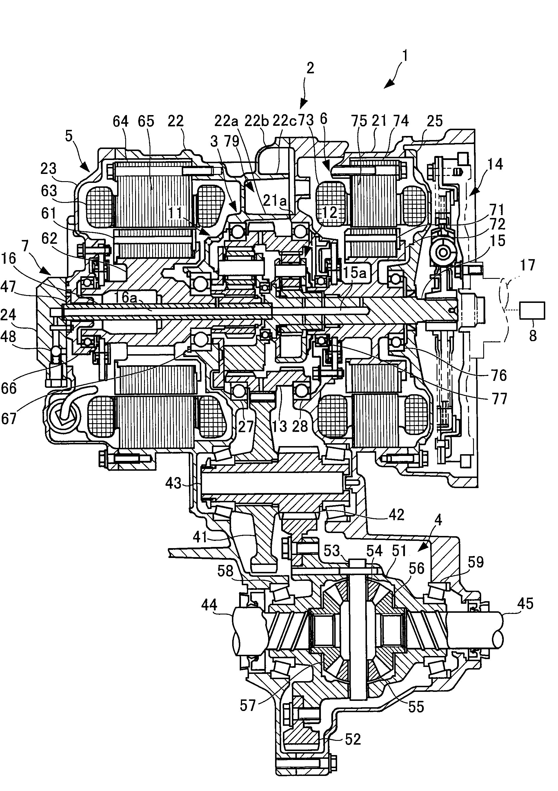
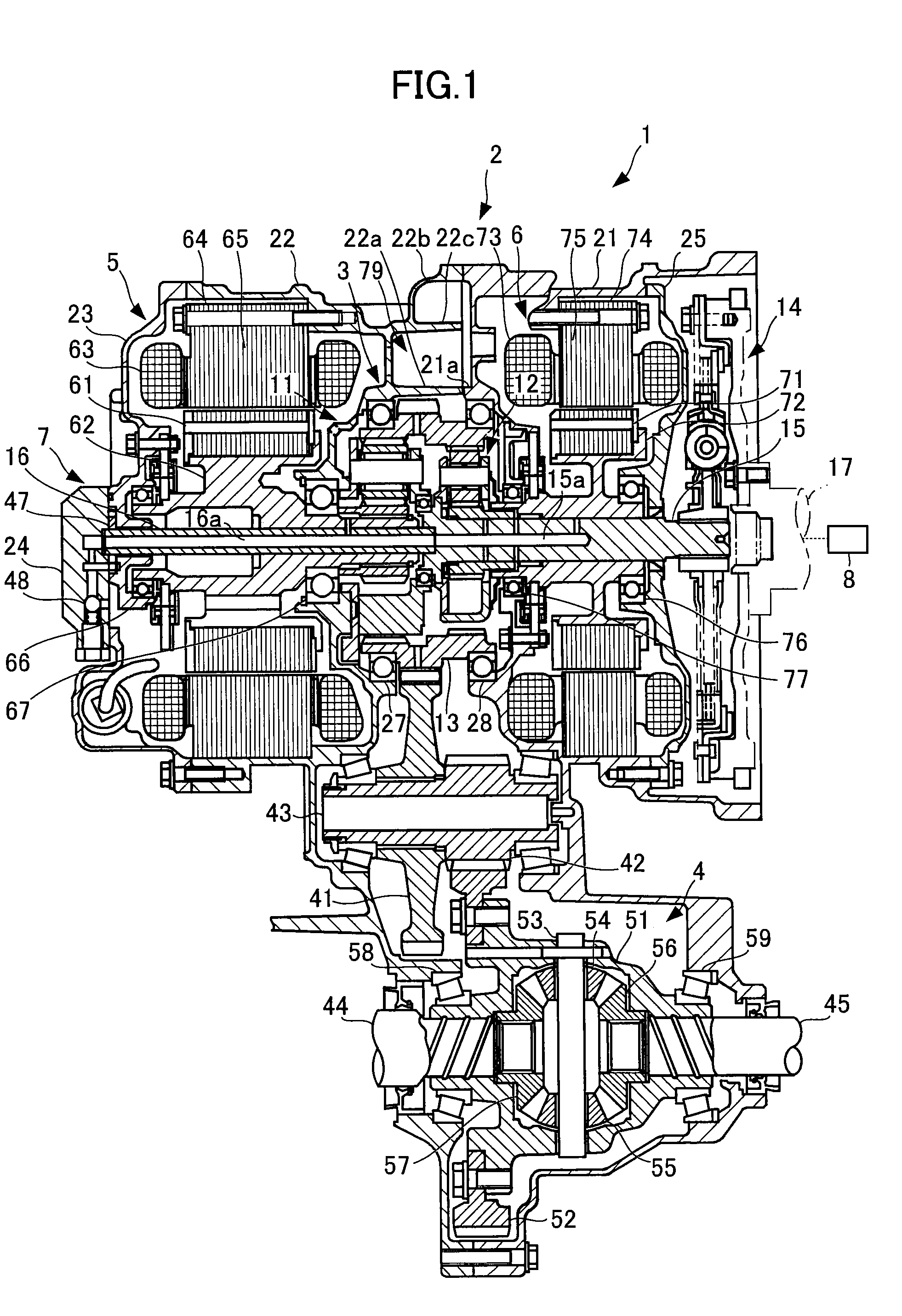
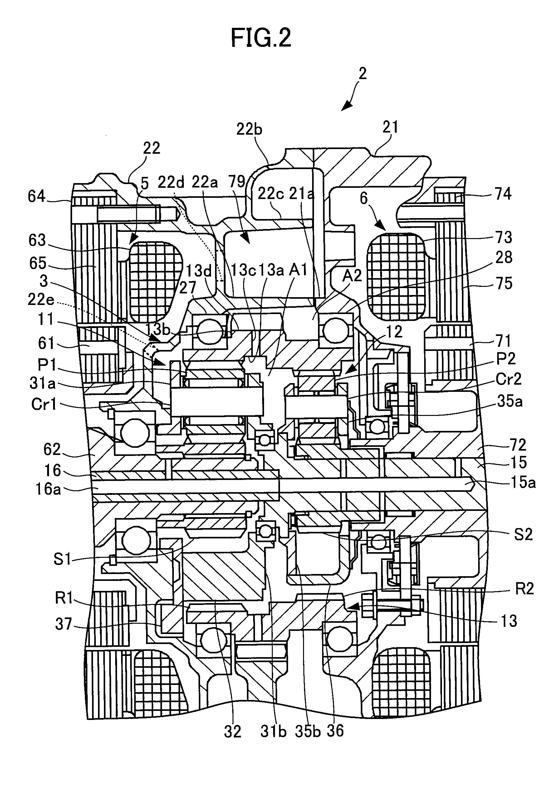
[0026]FIG. 1 is a cross-sectional view of a drive power transmission apparatus, showing a first embodiment of a composite planetary gear apparatus according to the present invention. FIG. 2 is an enlarged and fragmentary cross-sectional view of FIG. 1, showing the first embodiment of the composite planetary gear apparatus according to the present invention.

[0027]In FIGS. 1 and 2 is shown a drive power transmission apparatus 1 which comprises a transmission case 2 accommodating therein a composite planetary gear apparatus 3 constituting part of a change speed mechanism, a differential apparatus 4 capable of outputting differential output drive powers to respective front drive shafts 44 and 45, a drive motor 5 for driving an automotive vehicle with an electric power accumulated in a battery, a motor generator 6 capable of generating the electric power with a drive power outputted by an engine 8, and an oil pump 7 for pumping and feeding an oil to the parts and elements forming the dri...

second embodiment

[0076]FIG. 4 is an enlarged and fragmentary cross-sectional view similar to FIG. 3 for explaining the oil stirring state to be carried out in the second embodiment of the composite planetary gear apparatus according to the present invention.

[0077]The composite planetary gear apparatus 90 according to the second embodiment of the invention comprises sun gears not shown, pinion gears P3, P4, and ring gears R3, R4 which respectively constitute a first planetary gear assembly 91 and a second planetary gear assembly 92. The sun gears, the pinion gears P3, P4, and the ring gears R3, R4 of the first planetary gear assembly 91 and the second planetary gear assembly 92 are entirely the same in construction as the sun gears S1, S2, the pinion gears P1, P2, and the ring gears R1, R2 of the first planetary gear assembly 11 and the second planetary gear assembly 12 in the first embodiment of the composite planetary gear apparatus 3 shown in FIGS. 1 to 3.

[0078]However, the shapes of the sun gears...


PUM


Abstract

The composite planetary gear apparatus according to the present invention can bring about an advantageous effect to prevent fuel efficiency from being lowered stemming from the increased stirring loss of oil. The apparatus comprises a first planetary gear assembly 11 having a sun gear S1, pinion gears P1, and a ring gear R1, and a second planetary gear assembly 12 having a sun gear S2, pinion gears P2, and a ring gear R2. The ring gears R1 and R2 surround the pinion gears P1 and P2 and are combined together to integrally form a counter drive gear 13. The counter drive gear 13 is formed with a plurality of through bores 13c each having an inner end opened at a closed space defined by the first and second planetary gear assemblies 11 and 12, and an outer end opened at an outer space surrounding the counter drive gear 13.

Description

BACKGROUND OF THE INVENTION[0001]1. Field of the Invention[0002]The present invention relates to a composite planetary gear apparatus, and in particular to a composite planetary gear apparatus incorporating therein two planetary gear assemblies for reduction of the rotation speed of a drive power shaft having a drive power outputted by an engine.[0003]2. Description of the Background Art[0004]Up until now, there has been known as a prior-art composite planetary gear apparatus of this kind an apparatus to be mounted on a hybrid automotive vehicle, for example, by a following patent document. The known composite planetary gear apparatus is constituted by a first planetary gear assembly used for reduction of the output speed of a drive motor, and a second planetary gear assembly having a drive power distribution function to distribute a drive power outputted from an engine to a motor generator and to a counter drive gear serving as an integral part of outer ring member. The first plane...

Claims


Application Information

Patent Timeline
IPC IPC(8): F16H57/04F16H48/10F16H57/08
CPCB60K1/02B60K6/365B60K6/445Y02T10/6239F16H57/0409F16H57/0431F16H57/0486B60K6/547Y02T10/62
Inventor TOMITA, MAKOTOICHIOKA, EIJI
Owner TOYOTA JIDOSHA KK
Learn More