
Faraday Rotator Mirror and Method for Manufacturing the Same

Inactive Publication Date: 2009-09-17
KYOCERA CORP
View PDF6 Cites 6 Cited by
  • Summary
  • Abstract
  • Description
  • Claims
  • Application Information

AI Technical Summary

Benefits of technology

[0018]The Faraday rotator mirror 321 also requires it to optically align the optical fiber 322, the coupling lens 323 and the reflector mirror 326 with high precision. This results in such problems that it requires a larger number of processes, complicated assembly process and longer time for manufacturing the Faraday rotator mirror 321.
[0023]An object of the present invention is to solve these problems of the prior art and provide a Faraday rotator mirror which is compact, allows good workability, and has high reliability and high coupling efficiency.Means for Solving Problem
[0043]The Faraday rotator mirror of the present invention is constituted by using the graded-index fiber instead of the conventional lens or the enlarged-core fiber, and therefore is compact, has high coupling efficiency can be manufactured easily.
[0044]Since the Faraday rotator mirror of the present invention includes the optically compatible adhesive or the spacer, characteristics (such as insertion loss) of the Faraday rotator mirror can be suppressed from degrading due to variability in length of the graded-index fiber and / or thickness of the Faraday rotator during manufacturing by, for example, controlling the thickness of the optically compatible adhesive or the shape of the spacer.
[0045]Further in the Faraday rotator mirror, as the surface of the optically compatible adhesive by the protective member including moisture absorbent, moisture can be suppressed from infiltrating the optically compatible adhesive even in an environment of high temperature and high humidity. As a result, since the optically compatible adhesive can be kept from deteriorating due to moisture, insertion loss of light can be suppressed from deteriorating due to, for example, misalignment of the optical fiber, Faraday rotator and reflector mirror.
[0046]As described above, the present invention is capable of providing the Faraday rotator mirror which is compact, has good workability during manufacturing, high reliability and high efficiency of coupling.

Problems solved by technology

With such an optical fiber sensor, however, such a problem may occur as fluctuation of the output interference fringe or disappearance of signal caused by an accidental change in the state of polarization of light due to birefringence taking place in the optical fiber.
The optical fiber amplifier system commonly uses an erbium-doped single mode fiber (several tens to several hundreds of meters long), and therefore suffers such problems that the state of polarization undergoes variation due to birefringence taking place in the optical fiber and the divergence of polarization mode which deteriorates the signal waveform in a long distance fiber-optic communications system.

Method used


Image

  • Faraday Rotator Mirror and Method for Manufacturing the Same
  • Faraday Rotator Mirror and Method for Manufacturing the Same
  • Faraday Rotator Mirror and Method for Manufacturing the Same

Examples


first embodiment

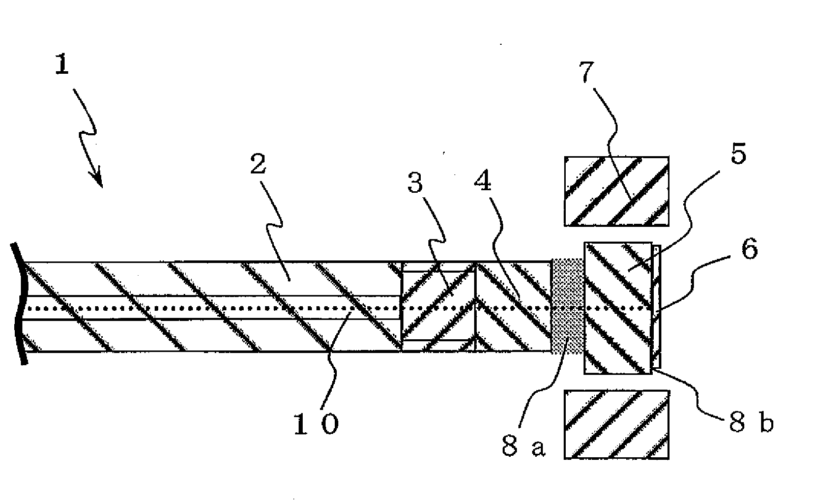
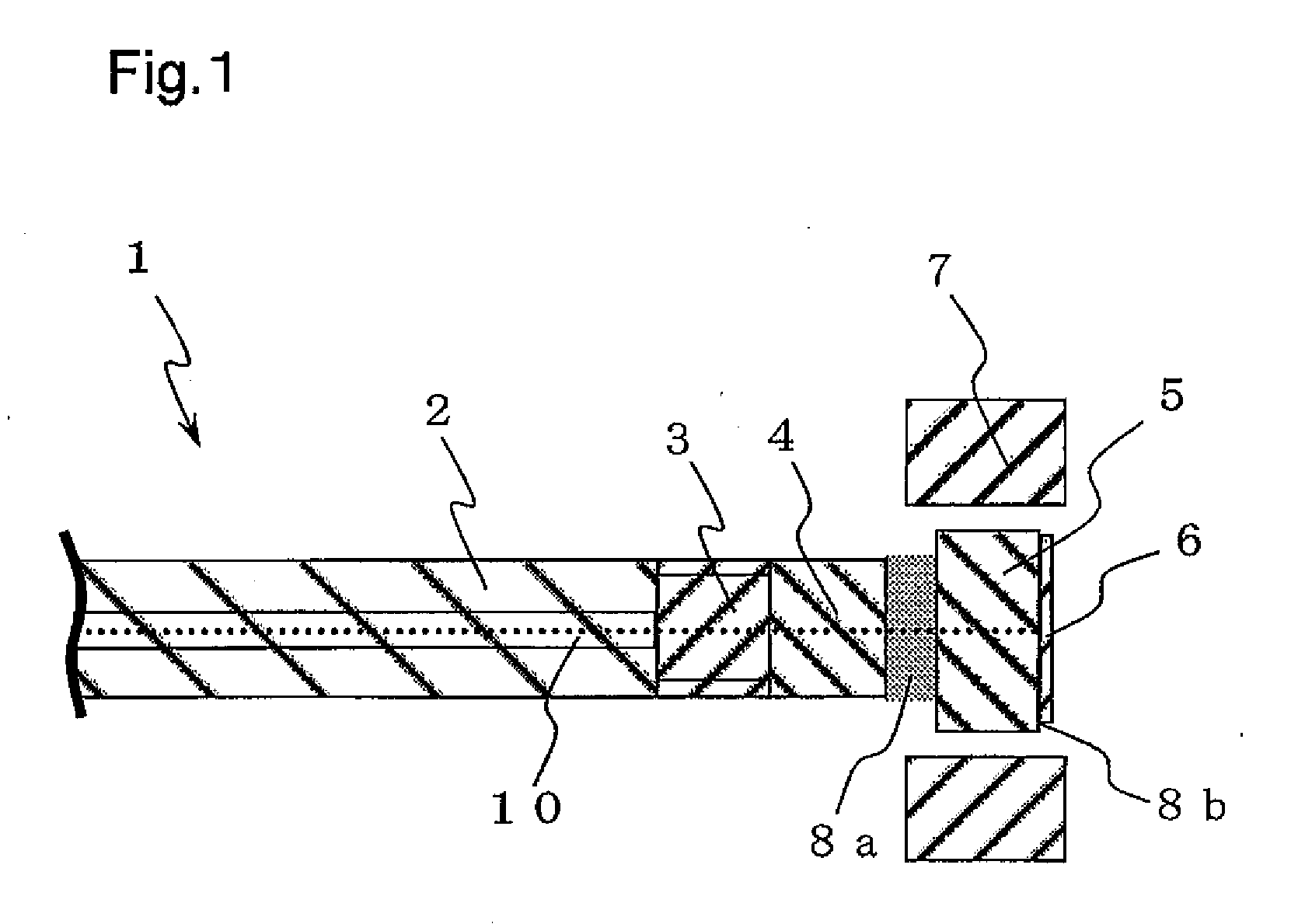
[0090]FIG. 1 is a sectional view schematically showing the constitution of a Faraday rotator mirror 1 according to the first embodiment of the present invention. The Faraday rotator mirror 1 comprises a single mode fiber 2, a graded-index fiber (GIF) 3, a coreless fiber 4, a Faraday rotator 5, a reflector mirror 6, the magnet 7 and optically compatible adhesives 8a, 8b.

[0091]The optical fiber 2 is for guiding light incident on one end thereof and letting the light emerge from the other end. The optical fiber 2 may be formed from quartz glass, multiple-component glass, plastics or the like.

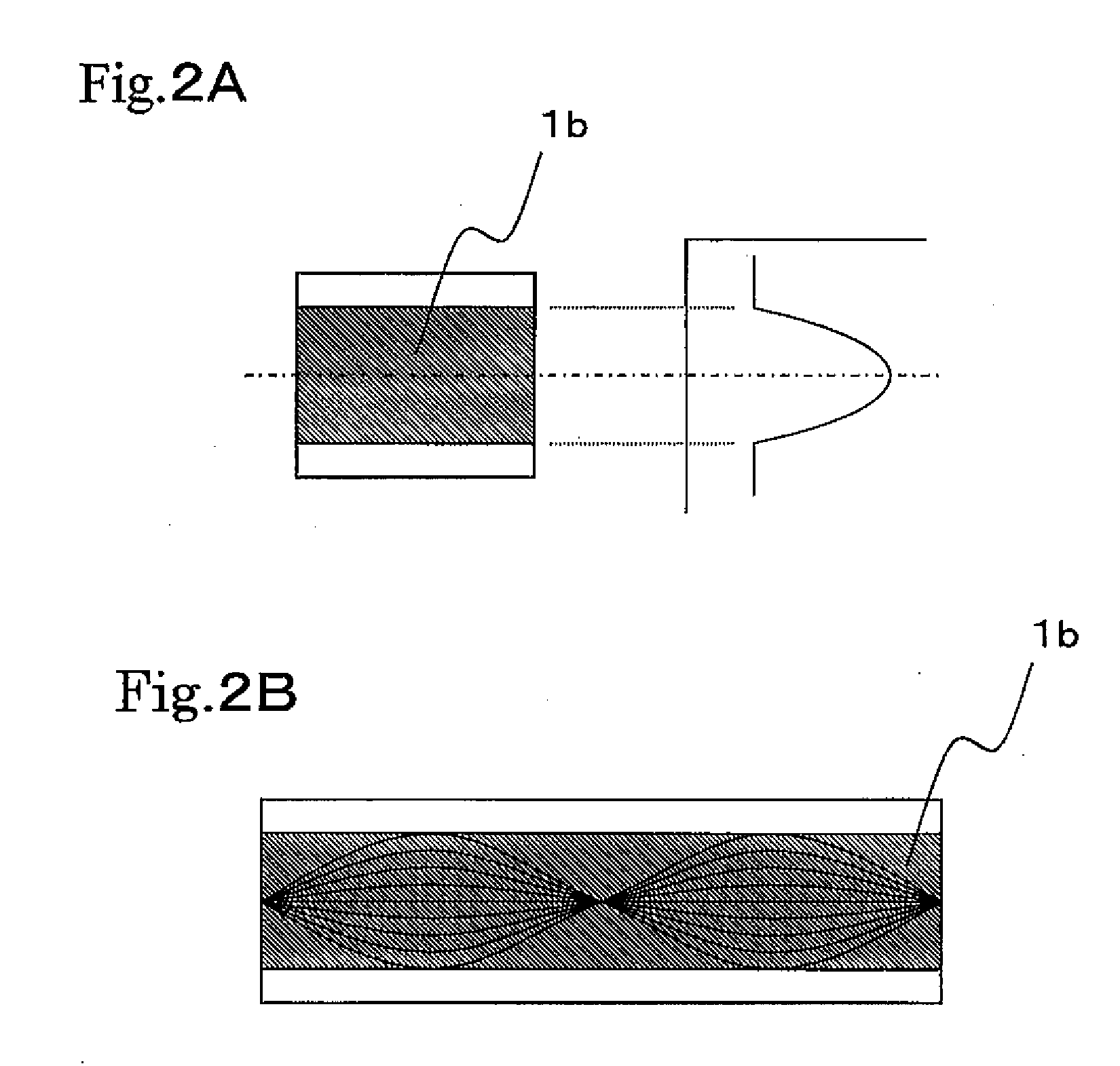
[0092]The graded-index fiber 3 is an optical fiber which has such a refractive index distribution that decreases stepwise or continuously from the center toward the circumference as shown in FIG. 2A, so that a light ray which passes through the fiber meanders periodically as shown in FIG. 2B. Therefore, light ray can be converged or collimated so that the fiber functions as a lens, by cutting the ...

second embodiment

[0114]FIG. 5 is a sectional view schematically showing the constitution of the Faraday rotator mirror 11 according to the second embodiment of the present invention.

[0115]The Faraday rotator mirror 11 of the second embodiment is different from the Faraday rotator mirror 1 of the first embodiment in the following points.

[0116](1) An end face of the coreless fiber 4 which opposes the Faraday rotator 5 is tilted from the plane perpendicular to the optical axis 10, and the Faraday rotator 5 is put into contact with the tilted face of the coreless fiber 4 via the optically compatible adhesive 8a.

[0117]As a result, the Faraday rotator 5 is also tilted from the plane perpendicular to the optical axis 10.

[0118](2) The optically compatible adhesive 8b is formed in wedge shape so as to dispose the reflector mirror 6 so that the principal surface (reflecting surface) thereof is perpendicular to the optical axis 10, and variations in machining of the graded-index fiber 3 and other component ar...

third embodiment

[0121]FIG. 7 is a sectional view schematically showing the constitution of the Faraday rotator mirror 12 according to the third embodiment of the present invention. The Faraday rotator mirror 12 of the third embodiment is constituted similarly to the Faraday rotator mirror 11 of the second embodiment, except that the single mode fiber 2, the graded-index fiber 3 and the coreless fiber 4 are held by a ferrule 13.

[0122]The Faraday rotator mirror 12 can be made structurally stable even when the fibers 2 through 4 have diameters (for example, 125 μm) smaller than the physical thickness (for example, 350 to 500 μm) of the Faraday rotator 5, by adjusting the mounting surface of the Faraday rotator 5 in the ferrule 13 to an optimum size (which is determined according to the physical thickness of the Faraday rotator 5). When forming the tilted surface on the coreless fiber 4 in the Faraday rotator mirror 12, it is possible to polish the coreless fiber 4 together with the ferrule 13, and the...


PUM

PropertyMeasurementUnit
Thicknessaaaaaaaaaa
Percent by massaaaaaaaaaa
Sound / signal amplitudeaaaaaaaaaa

Abstract

A Faraday rotator mirror which is compact, allows high workability of manufacturing and has high reliability and high coupling efficiency is provided. The Faraday rotator mirror comprises a graded-index fiber, a Faraday rotator and a reflector mirror, wherein light incident via the graded-index fiber passes through the Faraday rotator to be reflected on the reflector mirror, and the reflected light passes through the Faraday rotator and emerges through the graded-index fiber.

Description

FIELD OF THE INVENTION[0001]The present invention relates to a Faraday rotator mirror used as a passive optical component for the purpose of stabilizing the operation of optical fiber sensor system, optical amplifier system or the like, and a method for manufacturing the same.BACKGROUND OF THE INVENTION[0002]An optical fiber sensor is a system which consists mostly of an optical fiber and has a detecting element provided at some point in the optical path of the optical fiber. The detecting element is a component that undergoes a change in the characteristic thereof in accordance with a quantity of an object to be detected. For example, in case a single mode fiber is used as the detecting element for sensing an external disturbance such as vibration, pressure, temperature, electric field, magnetic field or acoustic vibration, the disturbance is detected by a fiber interferometer in the form of a change in the optical path of the single mode fiber caused by the external disturbance.[0...

Claims


Application Information

Patent Timeline
IPC IPC(8): G02F1/09B32B37/00
CPCG01R15/246G01R15/247G01R33/032G02B6/0281Y10T156/10G02F1/09G02F2201/02G02F2201/34G02B6/2746
Inventor TAKEI, YUSUKESUGA, TETSUYATOMIE, SATORUSATO, YASUSHISHODA, MICHIFUMI
Owner KYOCERA CORP
Learn More