Permanent magnet type generator and hybrid vehicle using the same

a permanent magnet generator and hybrid technology, applied in the direction of magnetic circuit rotating parts, propulsion by batteries/cells, magnetic circuit shape/form/construction, etc., can solve the problems of unstable operation of rotating electrical machines, and achieve low noise, small torque ripple, and low vibration

Inactive Publication Date: 2009-09-17
HITACHI LTD
View PDF7 Cites 55 Cited by
  • Summary
  • Abstract
  • Description
  • Claims
  • Application Information

AI Technical Summary

Benefits of technology

[0028]An advantage of the present invention is to provide a permanent magnet type motor generator which has small torque ripple, low noise, and low vibration by utilizing reluctance torque.
[0029]Moreover, the permanent magnet type motor generator according to the present invention can use any generator and motor, inner rotor and outer rotor, rotation type and linear type, and distributed stator winding.

Problems solved by technology

As a result, a torque ripple appears, causing a problem since the smooth rotation of the rotor is inhibited and operation of the rotating electrical machine becomes unstable.

Method used


Image

  • Permanent magnet type generator and hybrid vehicle using the same
  • Permanent magnet type generator and hybrid vehicle using the same
  • Permanent magnet type generator and hybrid vehicle using the same

Examples


Embodiment Construction

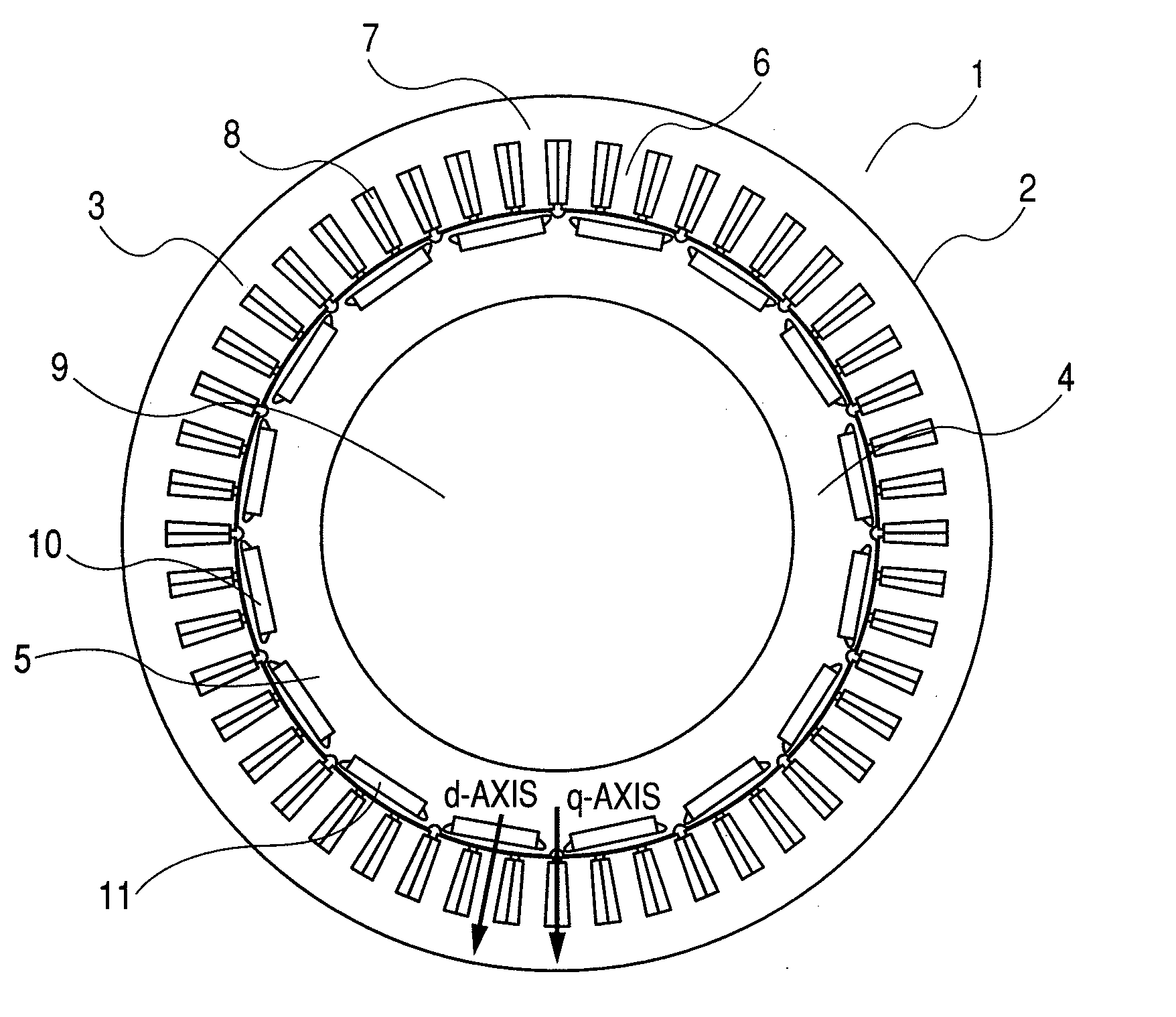
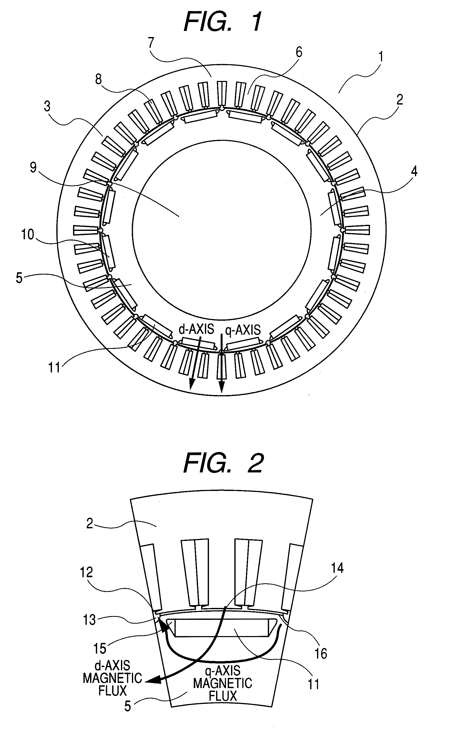
[0045]A permanent magnet type motor generator according to the present invention comprises a stator and a rotor which is disposed oppositely to the stator with a gap interposed. The stator comprises a stator core and a distributed stator winding mounted to the stator core. The stator core comprises a ring-like yoke core and a plurality of teeth cores which protrude from the yoke core in the radial direction. The rotor comprises a rotor core and a plurality of permanent magnets embedded in the rotor core. A pair of non-magnetic portions is created inside the rotor core and on both sides of the circumferential width of a permanent magnet for one magnetic pole. In the rotor core located on the stator side of the pair of non-magnetic portions, a pair of magnetic paths is created as the result of the creation of the pair of non-magnetic portions. Furthermore, a groove or hole is provided on the outer circumferential portion of the rotor core and between the adjacent magnetic poles.

[0046]...


PUM


Abstract

The present invention comprises a stator, and a rotor which is disposed oppositely to the stator with a gap interposed. The stator comprises a stator core, and a distributed stator winding mounted to the stator core. The stator core comprises a ring-like yoke core, and a plurality of teeth cores which protrude from the yoke core in the radial direction. The rotor comprises a rotor core, and a plurality of permanent magnets embedded in the rotor core. A pair of non-magnetic portions is created inside the rotor core and on both sides of the circumferential width of a permanent magnet for one magnetic pole. In the rotor core located on the stator side of the pair of non-magnetic portions, a pair of magnetic paths is created as the result of the creation of the pair of non-magnetic portions. Furthermore, a groove or hole is created on the outer circumferential portion of the rotor core and between the adjacent magnetic poles.

Description

CLAIM OF PRIORITY[0001]The present application claims priority from Japanese patent application serial No. 2008-063456, filed on Mar. 13, 2008, the content of which is hereby incorporated by reference into this application.FIELD OF THE INVENTION[0002]The present invention relates to a permanent magnet type generator and a hybrid vehicle that uses the permanent magnet type generator.BACKGROUND OF THE INVENTION[0003]Improved efficiency is required for a permanent magnet motor generator. Specifically, it is sometimes required that the power factor of a motor generator in a high-speed overload area be improved. With regard to a permanent magnet type motor generator, patent document 1 has disclosed the technology wherein when the magnetic flux axis of the permanent magnet is considered as a d-axis and an axis perpendicular to the d-axis is considered as a q-axis, the power factor can be increased by notching the q-axis side of the outer circumferential surface of the rotor core.[0004]Fur...

Claims


Application Information

Patent Timeline
IPC IPC(8): H02K1/27B60L50/16
CPCH02K1/246Y02T10/641H02K1/2766H02K21/14H02K29/03B60L7/14B60L11/123B60L11/14B60L15/2009B60L2210/40B60L2240/12B60L2240/423B60L2260/28B60L2270/145Y02T10/7077Y02T10/7241Y02T10/7275Y02T10/6217Y02T10/642H02K1/276B60L50/16B60L50/61Y02T10/62Y02T10/64Y02T10/70Y02T10/7072Y02T10/72
Inventor KAMIYA, AKINORIHINO, NORIAKITAJIMA, FUMIOMIYOSHI, TSUTOMUNIHEI, HIDEKI
Owner HITACHI LTD
Why Eureka
Try Eureka