
Insulated cleaning tool

a technology of cleaning tools and metal bodies, applied in the direction of flush cleaning, cleaning heat-transfer devices, cleaning using liquids, etc., can solve the problems of reducing the ability for good heat exchange and efficient operation, affecting the efficiency of cleaning, and endangering the safety of cleaning personnel, etc., to achieve efficient cleaning effect of fluidic jet, simple and convenient cleaning task, and convenient handling and manipulation

Inactive Publication Date: 2009-09-17
STONE RONALD K
View PDF3 Cites 10 Cited by
  • Summary
  • Abstract
  • Description
  • Claims
  • Application Information

AI Technical Summary

Benefits of technology

[0005]The primary object of the present invention is to provide a simple, strong, durable, economical and efficient cleaning tool having a wide variety of useful applications.
[0006]Another object is to provide a cleaning tool having an insulated, wand-like body member that can easily be handled and manipulated to efficiently effect fluidic jet cleansing.
[0007]Another object is to provide a simple, yet efficient cleaning tool that is completely portable and connectable to available water sources or other pressurized fluids, and which provides protected hand positioning and at the same time can be regulated as to fluidic cleaning pressure.
[0008]Another object is to provide a cleaning tool useful for electrically powered fixtures and is safety insulated to protect careless users who are unmindful of safety instructions and may be subjected to electrical shock.

Problems solved by technology

One of the most difficult and necessary cleaning tasks is that of air conditioning and refrigeration condenser coils, particularly of the type having closely spaced fins through which air passes to effect heat transfer.
Obviously the accumulation of dirt and debris in outdoor condenser units clogs the air passages and coats the fin and coil surfaces which greatly reduce the capability for good heat exchange and efficient operation.
However, despite safety warnings, users often do not turn off power to condensing units prior to initiating a cleaning function thereby endangering themselves to electric shock through the metal body of the tool.

Method used


Image

  • Insulated cleaning tool
  • Insulated cleaning tool
  • Insulated cleaning tool

Examples


Embodiment Construction

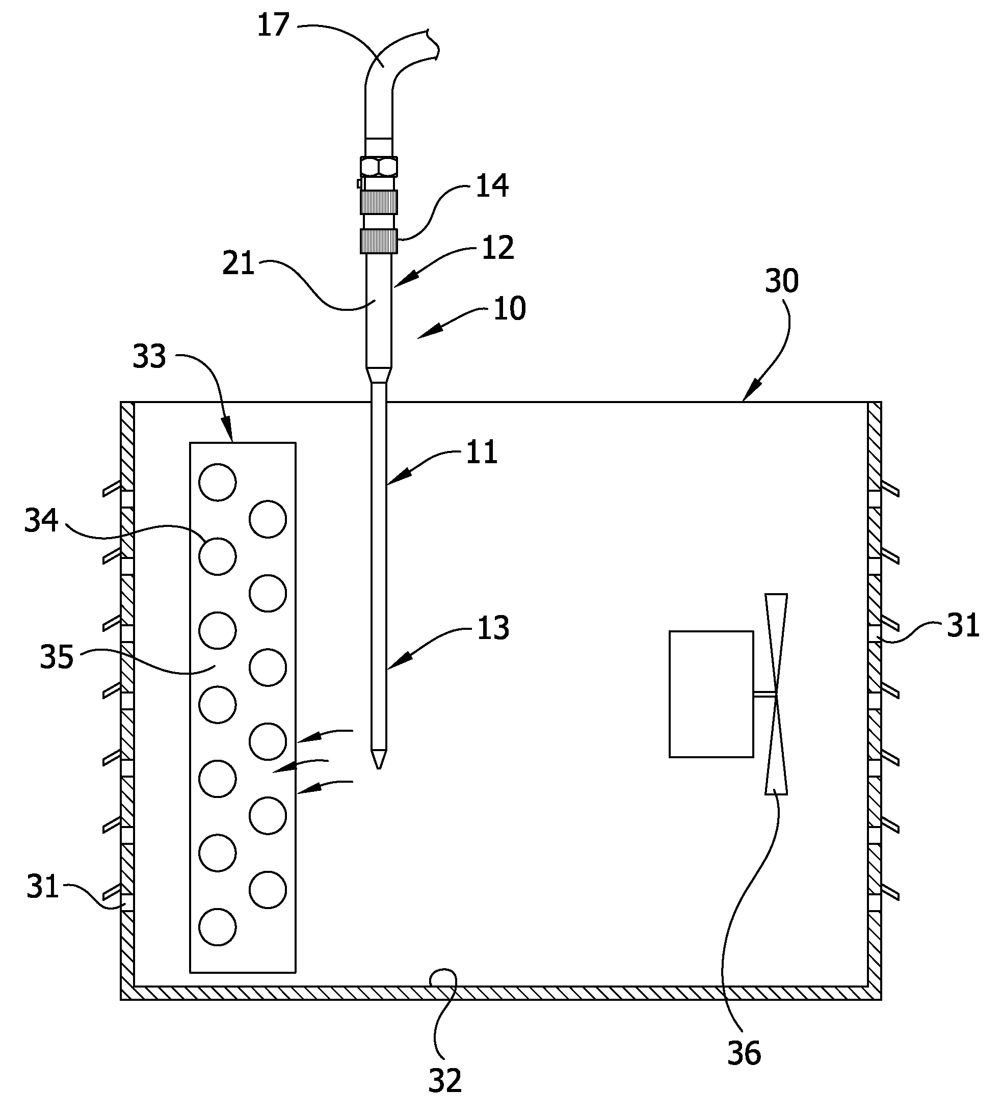
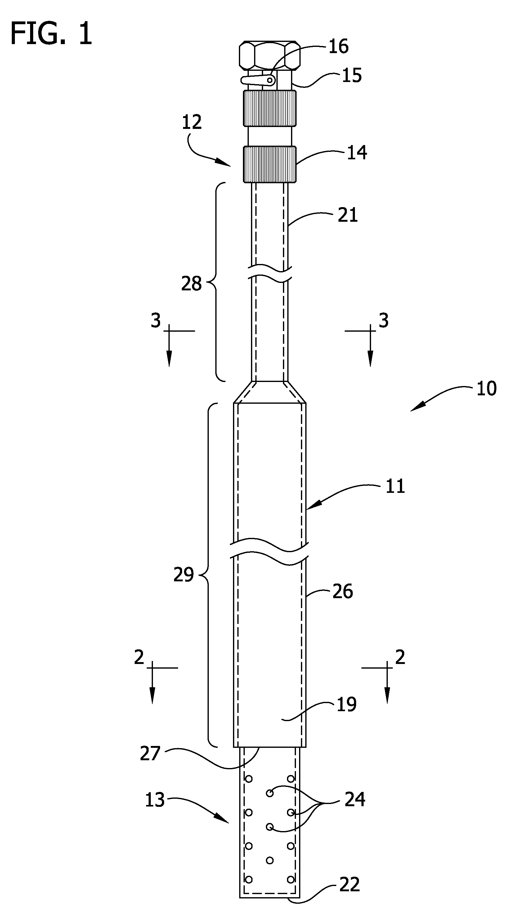
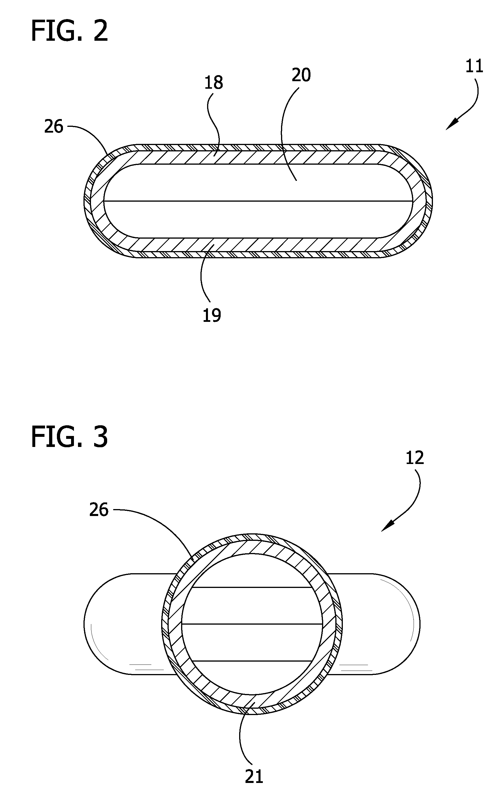
[0017]Referring now to the drawings, a cleaning tool 10 embodying the invention is illustrated, in which the tool 10 comprises a long main body 11 formed of aluminum conduit or like hollow, tubular material and having a fluid inlet section 12 at one end and a jet outlet section 13 at the other end. The fluid inlet end 12 has a non-metal fitting 14 of electrical insulating material adapted to connect the tool 10 to a fluid source (17), and has a valve member 15 with a control handle 16 by which the internal valve (not shown) may be entirely opened or closed to fluid flow or turned to regulate the volume of such flow. The tool 10 will work efficiently with different fluid cleaning mediums such as compressed air, carbon dioxide, and pressurized cleaning fluids such as carbon tetrachloride or the like, but a conventional city water hook-up is highly effective, economical, easy to use and always readily available. Thus, the tool 10 through valve 15 may be connected to a typical garden ho...


PUM


Abstract

A cleaning tool comprising a long thin body member having an upper valved end connectable to a pressurized source of cleaning fluid and having a closed lower end with a plurality of adjacent jet discharge ports, said body member being constructed and arranged with a first hand grip zone located at the upper end and a second hand grip zone located adjacent to the discharge ports, and the hand grip zones having an insulated safety covering.

Description

CROSS-REFERENCE TO RELATED APPLICATIONS[0001]This is a non-provisional of U.S. application Ser. No. 61 / 036,532, filed Mar. 14, 2008, the entire disclosure of which is incorporated herein by reference.FIELD OF THE INVENTION[0002]The present invention pertains generally to cleaning tools, and more particularly to tools for producing controlled high pressure fluidic jets for cleansing action.BACKGROUND OF THE INVENTION[0003]A great number of nozzles and tools for producing pressurized cleaning action have been designed in the past for doing a variety of cleaning jobs. One of the most difficult and necessary cleaning tasks is that of air conditioning and refrigeration condenser coils, particularly of the type having closely spaced fins through which air passes to effect heat transfer. Obviously the accumulation of dirt and debris in outdoor condenser units clogs the air passages and coats the fin and coil surfaces which greatly reduce the capability for good heat exchange and efficient ...

Claims


Application Information

Patent Timeline
Patent Type & Authority Applications(United States)
IPC IPC(8): B05B9/00
CPCB05B1/20B08B3/026F28G9/00F28G1/166B08B5/02
Inventor STONE, RONALD K.
Owner STONE RONALD K
Learn More