
Apparatus and Process for Biological Wastewater Treatment

a biological wastewater and multi-functional technology, applied in the field of biological wastewater multi-functional apparatus and process, can solve the problems of large energy consumption, large carbon footprint, complex, expensive and energy-intensive, etc., and achieve the effects of improving the stability and dependability of the system, preventing buildup, and excellent gas exchang

Active Publication Date: 2009-09-17
LIMCACO CHRISTOPHER A
View PDF9 Cites 74 Cited by
  • Summary
  • Abstract
  • Description
  • Claims
  • Application Information

AI Technical Summary

Benefits of technology

The invention is a multi-functional facility that can treat wastewater, reduce greenhouse gases, and produce valuable biomass. It uses algae to capture energy from wastewater treatment, which reduces the energy required for treatment. The facility is designed to be self-sustainable and can produce excess biomass for use outside the plant. It also has a shallow operating depth, eliminating the need for deep tanks and reducing the risk of injury. The invention can be used in wastewater treatment plants and is efficient in removing organic compounds from wastewater. Overall, the invention provides a more energy-efficient and safe way to treat wastewater and produce energy.

Problems solved by technology

Treatment processes now exist to meet these regulations, but the methods create significant GHGs, and are complex, expensive and energy intensive.
Obviously, that is not the case today.
Two major problems with current wastewater treatment technologies are their large energy consumption and large carbon footprint.
In addition to activated sludge and bio-film systems, there are over 5,100 pond type wastewater treatment systems in the U.S. The energy requirement for pond systems is typically lower at 0.4-1.4 MWh per MG but these types of systems are not capable of meeting current direct discharge regulatory requirements.
Pond systems also require large amounts of land and have large carbon footprints because they generate methane from anaerobic digestion in the bottom of the ponds.
For this reason, some regulatory agencies will no longer allow these types of systems at all.
Nitrogen and phosphorous removal is very difficult to achieve with an activated sludge or bio-film system and would add significantly to the capital cost of WWTPs as well as increase their energy consumption and GHG emissions.
Bio-film systems are not capable of efficiently growing algae or phototrophic bacteria because of mechanical problems and clogging.
However, like the bio-film systems, suspended growth systems are not capable of growing algae or phototrophic bacteria due to the high concentration of bacteria maintained in the system, typically referred to as mixed liquor suspended solids (MLSS) concentration.
The sludge handling at conventional WWTPs is extremely energy intensive, requires chemicals for dewatering and sludge stabilization, and uses fossil fuels to process and transport the sludge for final disposal.
Sludge that is land applied also creates public health hazards from fecal and pharmaceutical contamination of food crops.
The main problem with pumping CO2 underground is that the energy requirements make this approach impractical to implement.
Another problem is the risk that the gases will escape to the surface.
We have no idea what the future consequences of such actions would cause.
Carbon sequestration via algae based systems is also impractical.
However, these alternative energy sources cannot cost effectively and reliably produce electricity and do not appear to have the near-term capability of satisfying the need for petroleum-type fuels—i.e., gasoline and diesel fuels.
Of course, one significant limitation of this technology is that it is tied to a source of waste CO2.
Another detriment is that this proposed technology requires a large raceway pond, and ultimately a large amount of dedicated land in order to support enough algae to accept the waste CO2 and to produce a meaningful amount of algae for biofuel production.
The large size of the pond also means that the useful “season” is limited in certain locales and climates due to freezing of the pond.
There currently are no algae production systems in the world that can replace a conventional extended aeration system and achieve the same level of treatment.
Some algae production systems have been proposed on WWTP effluent but that provides little benefit to the treatment plant owner because the wastewater has already been cleaned.
In fact, it creates a major liability and risk to the owner because of the potential re-contamination with algae solids with certain types of algae production systems.
High rate algae ponds have been used for wastewater treatment but pond systems are not capable of meeting current regulatory discharge requirements and require very large amounts of land as compared to mechanical WWTPs.
One reason why current algal production systems cannot be used to treat wastewater is due to the fact that algae cannot use organic carbon as a carbon source.
Current algae production systems lack a bio-media component to provide the growing means for the bacteria required for this conversion to take place.
Another problem with growing algae in any kind of pond is that only in the top ¼ inch or so of the water does the algae receive enough solar radiation.
Thus, the ability of the pond to grow algae is limited by its surface area, not by its volume.
These systems had obvious limitations, such as land space, geography and topography, water clarity, etc.
In addition, the lagoon systems were prone to algae blooms that would overrun and clog the systems.
These limitations led to the development of the algae raceway in the 1970s.
One significant detriment of the algae raceway is that it requires a large surface area for adequate exposure to sunlight.
In addition, the raceway requires a shallow water level to function, which inherently limits the volume and flow of wastewater that can be treated by any particular raceway facility.
Still another problem with ponds and raceway systems is predation by animals and insects.
The larvae of some insects feed on the algae and can consume the entire crop of algae almost overnight.
One of the disadvantages of closed bioreactors is that as the algae increases in the container, the uniform light distribution throughout decreases due to the light being absorbed by the algae.
The outermost layer of algae in the reactor get too much light and the inner layer of algae do not have enough light.
Algae also produces organic compounds that coat the closed bioreactor and slowly reduce the ability of light to penetrate the bioreactor.
The bioreactor material has to be either cleaned or replaced increasing operation and replacement costs.
Currently proposed closed bioreactors cannot be used with typical exhaust blowers found at coal plants due to the water depth of the reactors which creates too high of a pressure head for the blowers to pump against.
Still another problem in closed loop bioreactors is gas buildup.
Since the reactors are completely closed and CO2 is being compressed into the growing container, gas concentrations can build to levels that are toxic to the algae and that are detrimental to the equipment.
Another problem with closed loop bioreactors is the amount of energy required to move the water through the system, especially the vertical algae growing systems.
This is essentially the same problem ethanol plants have encountered by consuming more energy than energy produced.
Heat buildup is another problem with closed loop bioreactors.
Ultimately, closed loop bioreactors are poor substitutes for conventional wastewater treatment processes.

Method used


Image

  • Apparatus and Process for Biological Wastewater Treatment
  • Apparatus and Process for Biological Wastewater Treatment
  • Apparatus and Process for Biological Wastewater Treatment

Examples


Embodiment Construction

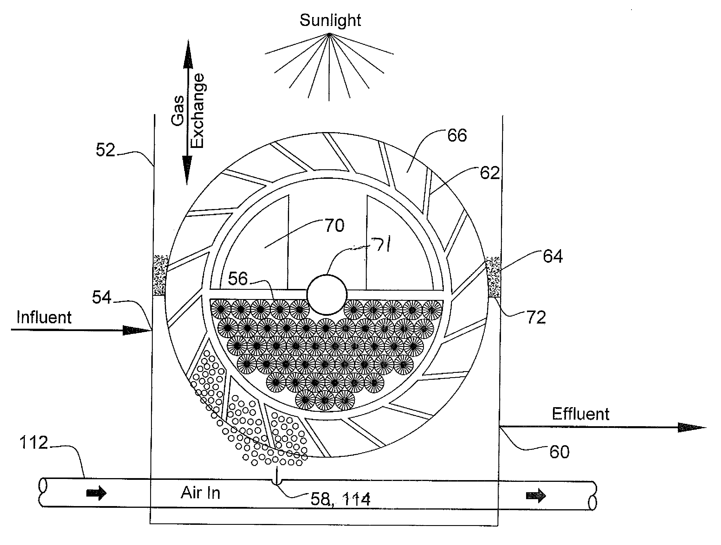
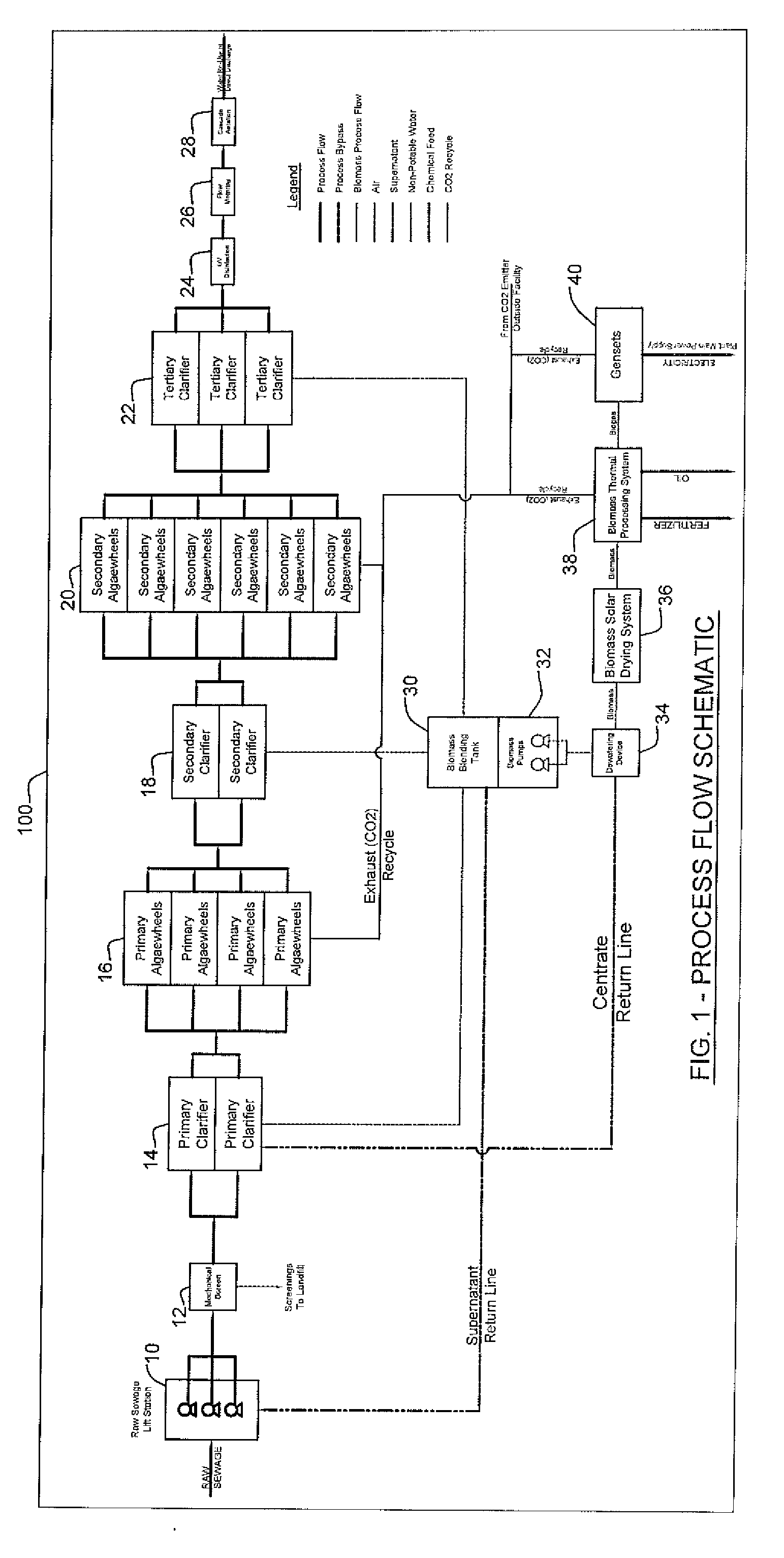
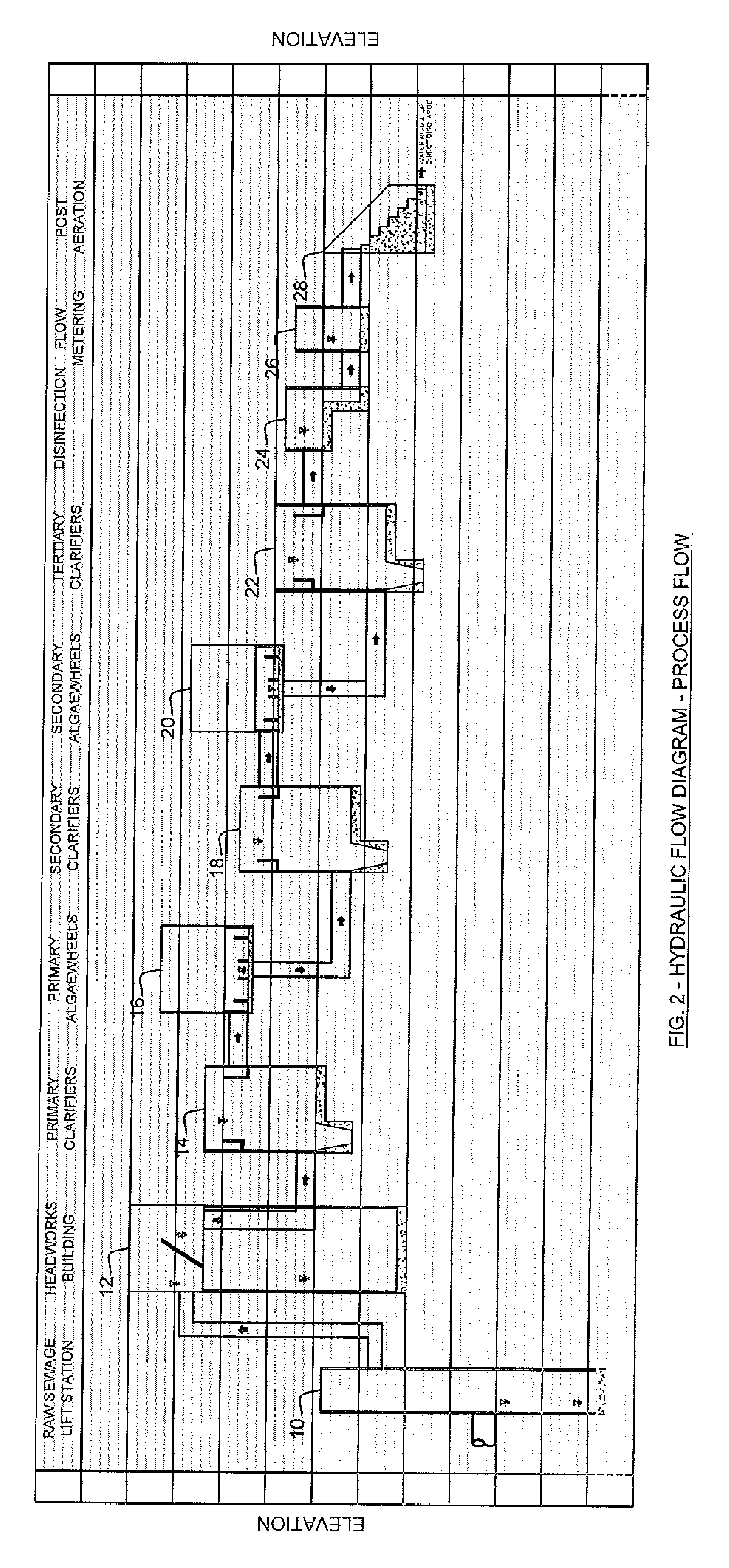
[0059]For the purposes of promoting an understanding of the principles of the invention, reference will now be made to the embodiments illustrated in the drawings and described in the following written specification. It is understood that no limitation to the scope of the invention is thereby intended. It is further understood that the present invention includes any alterations and modifications to the illustrated embodiments and includes further applications of the principles of the invention as would normally occur to one skilled in the art to which this invention pertains.

[0060]Algae have never been successfully used for primary and secondary treatment in wastewater treatment plants because algae must have light for a large portion of the time to grow. During daylight hours algae gives off oxygen as a by-product and at night it produces carbon dioxide. If all light is cut off, it will ultimately die. Wastewater is so turbid that algae never forms in treatment plants in sufficient...


PUM

PropertyMeasurementUnit
water depthaaaaaaaaaa
energy consumptionaaaaaaaaaa
energyaaaaaaaaaa

Abstract

A self-sustaining wastewater treatment facility abates greenhouse gas abatement, captures CO2 and produces biomass to address multiple critical environmental needs. The facility includes an array of rotating media wheels that create an optimum ordered mixing of algae for sustained growth. Biomass harvested from the rotating media wheels may be provided to other processing facilities to produce, for instance, bio-fuels. Waste CO2 from the processing facility may also be returned to the treatment system for enhanced algae growth. Bacteria are provided to form a symbiotic relationship with the algae, fueled by sunlight to effectively remove toxic materials from the wastewater. The multi-functional facility may also be integrated into a regenerative facility in which the biomass obtained from the algal and bacterial colonies is used in a separate facility and byproducts of the operation of the separate facility are used by the multi-functional facility to fuel further algal growth.

Description

REFERENCE TO RELATED APPLICATION[0001]This application is a continuation-in-part of and claims priority to application Ser. No. 11 / 957,648, filed on Dec. 17, 2007, entitled “System and Method for Biological Wastewater Treatment and Using the Byproduct Thereof”, which is a continuation-in-part of and claims priority to application Ser. No. 11 / 856,175, filed on Sep. 17, 2007, which claims priority to provisional patent application No. 60 / 845,490, filed on Sep. 18, 2006.BACKGROUND[0002]The present invention provides a multi-functional apparatus and process for biological wastewater treatment. The present invention addresses multiple critical environmental needs, including energy efficient treatment of wastewater, abatement of greenhouse gases (GHGs) produced from conventional wastewater treatment processes, CO2 capture from CO2 generators, and biomass production for renewable energy, fertilizer, feed additive, bio-plastics, cosmetics, pharmaceuticals, fabrics, bio-fuels, and other uses...

Claims


Application Information

Patent Timeline
Patent Type & Authority Applications(United States)
IPC IPC(8): C02F3/08
CPCC02F1/32C02F1/76C02F3/082C02F3/32C02F2209/40Y02E50/343C10L3/08C10L5/46Y02E50/10Y02E50/30C05F17/0018Y02W10/37Y02P20/145C05F17/40Y02W30/40Y02W10/10
Inventor LIMCACO, CHRISTOPHER A.
Owner LIMCACO CHRISTOPHER A
Learn More