
Method and Device for Acoustic Manipulation of Particles, Cells and Viruses

Inactive Publication Date: 2009-09-10
FRAUNHOFER GESELLSCHAFT ZUR FOERDERUNG DER ANGEWANDTEN FORSCHUNG EV
View PDF4 Cites 67 Cited by
  • Summary
  • Abstract
  • Description
  • Claims
  • Application Information

AI Technical Summary

Benefits of technology

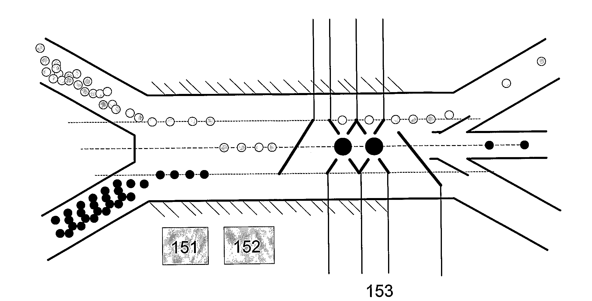
[0008]An object of the present invention is to provide a method and a device for non-intrusively manipulating suspended particles and / or cells and / or viruses, which allow a more efficient coupling of acoustic energy into the channels, a better control of the standing and / or stationary acoustic waves along the channels or chambers and the possibility of observation of the particles and / or cells and / or viruses by optical transmission microscopy during manipulation.
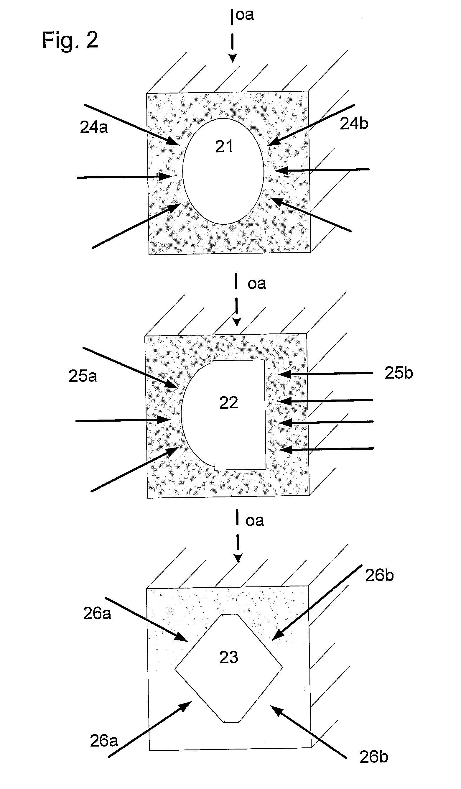
[0017]In other words, a main idea of the present method and device is to couple the acoustic field into the inner volume of the micro-channel primarily horizon-tally, thereby increasing the coupling efficiency to relevant acoustic modes in the channel significantly and allowing for further optical investigation during manipulation through an optical transmission path in the vertical direction. The horizontal or lateral coupling refers to any geometric assembly of the acoustic transducers which allows the part of the micro-channel in which the particles are to be manipulated to be optically transparent in a vertical direction, i.e. the field of view not being obstructed by the acoustic transducers. In the case of commonly used micro-system designs as described above, this refers in particular to any geometric assembly, where the main propagation axis of the incident acoustic wave is primarily perpendicular or deviating only in a small angle from a perpendicular direction to the inner surfaces of the lateral walls of a rectangular or otherwise shaped micro-channel.
[0019]With the present method and device several different acoustic transducers can be placed at different positions along the micro-channel, thereby allowing different manipulation to be performed at different regions along the channel. Furthermore, by changing the frequency of the transducer, different node patterns in the channel can be created, allowing fast switching and, thus, manipulation. When using the channel walls as a resonant cavity for the acoustic wave, it is important that the resonator formed by the walls of the channel has the correct dimension with respect to the frequency of the acoustic wave. The horizontal coupling using refractive elements as coupling elements allows optical transmission microscopy to be performed at the time of manipulation, since no acoustic transducer covers the channel. The method is compliant with all-glass or glass-Si-glass structures allowing optical transmission microscopy in line. The method is also compliant with other materials of the substrate and of the top and bottom layer.
[0024]An advantage of the combination of DEP and acoustic manipulation is that less DEP forces are needed for manipulation, resulting in less potential damage of in particular cells or viruses. The flexibility of use of the two independent forces allows an accurate manipulation of the particles.

Problems solved by technology

Conventional micro-systems have disadvantages in relation to the effectiveness of generating the polarization forces.
This relates in particular to the stability and longevity of the microelectrodes as well as to a limited ability of generating force gradients within the channel structure.
These disadvantages are in particular linked to the electrode bands which are formed over comparatively long distances in the channel.
However, long electrode bands are also more susceptible to malfunction.
Faults in workmanship or mechanical loads can cause interruptions of these bands which lead to electrode failure.
Due to these disadvantages the application of fluidic micro-systems with dielectrophoretic particle manipulation has been limited to the guidance of particles in the channel structure or to the deflection of particles from a given flow.
Disadvantages of this technology are the required high external apparatus which hinders miniaturization, and the energy deposition into the material in the focal spot.
One of the problems arising with this acoustic manipulation is the coupling efficiency of the acoustic waves into the inner volume of the micro-channels or micro-chambers, which often have only a small height compared with their lateral dimensions. F. Peterson et al., “Separation of Lipids from Blood Utilizing Ultrasonic Standing Waves in Micro-Fluidic Channels”, Analyst, 2004, 129, pp.
The acoustic techniques proposed in the above documents, however, are nevertheless lacking an efficient coupling of energy into the channels.
Furthermore, the control of the ultrasonic standing and / or stationary wave fields along the channels is very limited.
The described acoustic setups also do not directly allow for transmission optical microscopy to observe the particles or cells in the channels during manipulation.

Method used


Image

  • Method and Device for Acoustic Manipulation of Particles, Cells and Viruses
  • Method and Device for Acoustic Manipulation of Particles, Cells and Viruses
  • Method and Device for Acoustic Manipulation of Particles, Cells and Viruses

Examples


Embodiment Construction

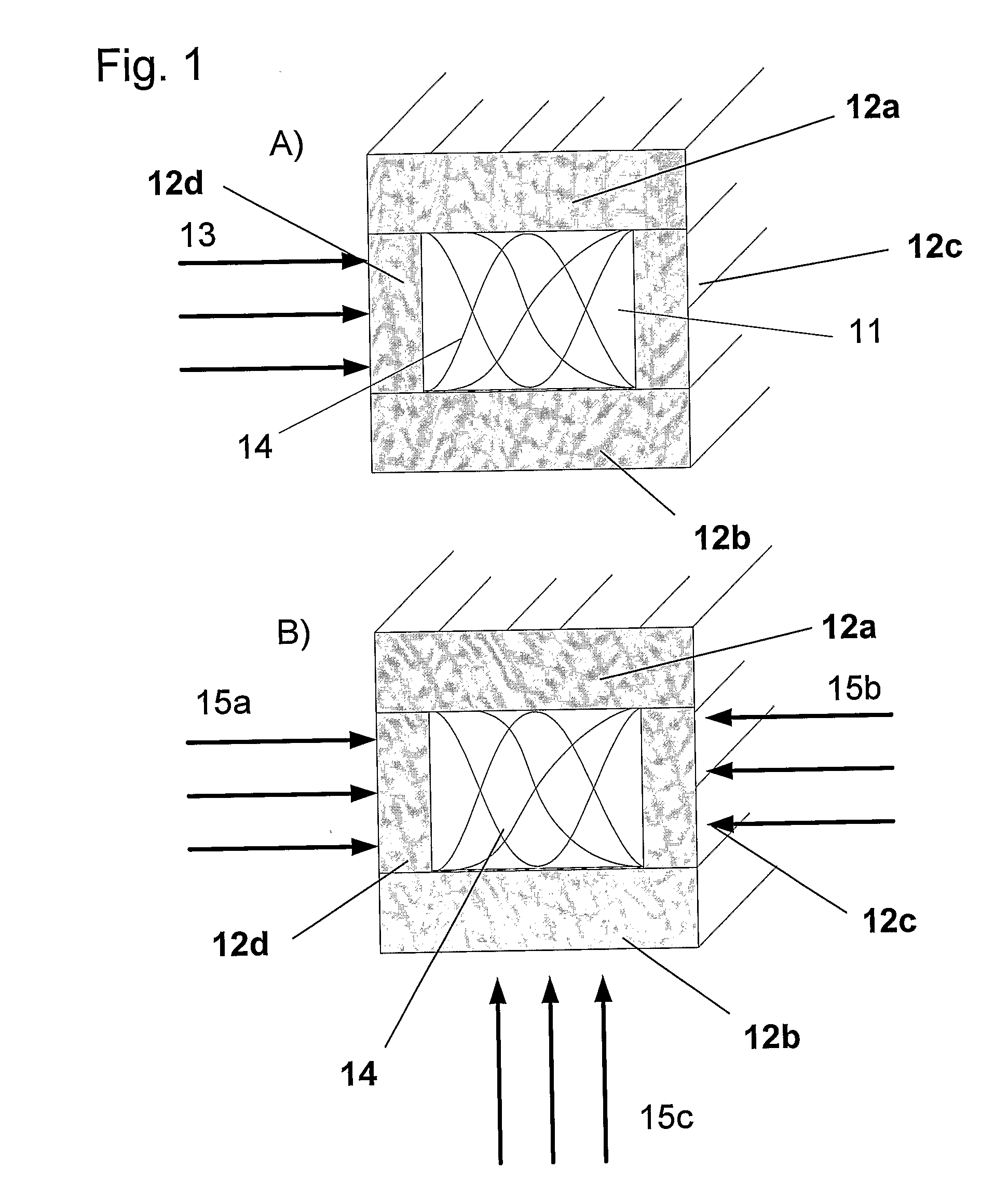
[0045]FIG. 1 shows a schematical side view of a micro-channel 11 which is embedded in a surrounding material forming a top wall 12a, a bottom wall 12b and lateral walls 12c, 12d. An acoustic wave 13 is applied laterally to the inner volume of said micro-channel 11 as indicated in FIG. 1a. The inner surfaces of the walls 12a-12d of the micro-channel 11 are reflecting surfaces for the acoustic wave. With the distance of these inner surfaces adapted to the wavelength of the acoustic wave, a standing and / or stationary acoustic wave 14 forms in this micro-channel 11 as shown schematically in FIG. 1. The micro-channel 11 then serves as a resonating cavity for the acoustic wave to generate the standing and / or stationary wave 14. It is evident that the wavelength of the acoustic wave 13 also depends on the medium inside of this micro-channel 11, in particular of the type of fluid supplied to this micro-channel 11. As a rule, the frequency of the applied acoustic wave 13 is tuned appropriate...


PUM


Abstract

The present invention relates to a method and device for non-intrusively manipulating suspended particles and / or cells and / or viruses, which are supplied to a micro-chamber or to a micro-channel (46) of a substrate, said micro-chamber or micro-channel (46) having at least a bottom wall as well as lateral walls. At least one acoustic wave (41) is applied via at least one acoustic transducer (42, 44) from outside of said substrate to an inner volume of said micro-chamber or micro-channel (46), a frequency of said acoustic wave (41) being selected to generate a standing and / or stationary acoustic wave in said volume. In the present method and device the acoustic wave (41) is applied laterally to said volume. The present device and method allow an efficient coupling of energy into the channels as well as an improved control of standing and / or stationary acoustic wave fields along the channels. Furthermore the device and method allow for transmission optical microscopy to observe the manipulated particles in the channels during manipulation.

Description

FIELD OF THE INVENTION[0001]The present invention relates to a method and device for non-intrusively manipulating suspended particles and / or cells and / or viruses, which are supplied to a micro-chamber or to a micro-channel of a substrate, said micro-chamber or micro-channel having at least a bottom wall as well as lateral walls, wherein at least one acoustic wave is applied via at least one acoustic transducer from outside of said substrate to an inner volume of said micro-chamber or micro-channel, a frequency of said acoustic wave being selected to generate a standing acoustic wave in said volume.[0002]A non-intrusive separation, positioning, concentration or other manipulation of particles and / or cells and / or viruses in micro-channels or micro-chambers is required in various technical fields including applications in bio-technology and cell-biology.BACKGROUND OF THE INVENTION[0003]It is known that suspended particles or cells can be non-intrusively handled in micro-channels and mi...

Claims


Application Information

Patent Timeline
IPC IPC(8): C12N13/00C12M1/42
CPCB01L3/502715B01L3/502761B01L3/502776C12M33/00B01L2300/168B01L2400/0439B01L2300/0645
Inventor LEMOR, ROBERTGUNTHER, CHRISTIANFUHR, GUNTERWIKLUND, MARTINHERTZ, HANS
Owner FRAUNHOFER GESELLSCHAFT ZUR FOERDERUNG DER ANGEWANDTEN FORSCHUNG EV
Learn More