
Photosensitive planographic printing plate and fabrication process thereof

Inactive Publication Date: 2009-09-10
FUJIFILM CORP
View PDF4 Cites 5 Cited by
  • Summary
  • Abstract
  • Description
  • Claims
  • Application Information

AI Technical Summary

Benefits of technology

[0025]In consideration of the circumstances described above, an object of the present invention is to provide a photosensitive planographic printing plate which can avoi

Problems solved by technology

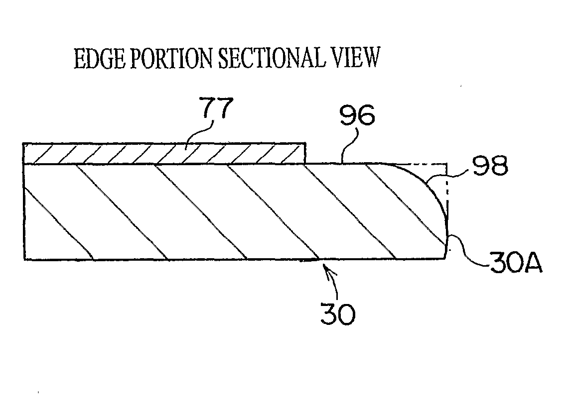
As a result, in newspaper printing using an offset roller, ink that adheres to a cut edge (an “ledge portion”) of the PS plate is printed onto and soils the printing paper (“edge soiling”), and commercial value of the printed product is adversely affected.
In the aforementioned process of forming cutaway portions along edge portions of a support, it is necessary to extract the PS plates one at a time to form the cutaway portions, which is unsuitable for mass processing.
Furthermore, when defects which will lead to adherence of ink occur, such as burrs, scratches and the like, ink gets caught at regions at which such defect portions are formed, and ultimately printing paper surfaces are stained with this ink.
Further, with a process of applying a desensitization fluid to cut faces, the PS plates may adhere together and handling may be adversely affected, which may lead to development problems.
Further again, although a shape in which cutting edge portions are curved downward (to a side opposite from the printing surface) tends to ameliorate soiling, there is a problem with the PS plate getting stuck during conveyance by a platemaking machine which performs exposure and development, or the like, and conveyance failures may result.
Therefore, consequent to variations in conditions of shearing blade abrasion and the like, problems may arise with burrs, cracks in an oxidation layer and the like.
When large burrs form at, for example, a rear face (a face at the opposite side from the face at which a surface processing layer is formed), problems arise in that the PS plate meanders when the PS plate is being conveyed in an exposure device, the burrs drop off and become waste matter, and so forth.
Moreover, at a time of shearing, large cracks are formed at a front face (the face at which th

Method used


Image

  • Photosensitive planographic printing plate and fabrication process thereof
  • Photosensitive planographic printing plate and fabrication process thereof
  • Photosensitive planographic printing plate and fabrication process thereof

Examples


Example

[0168]The results were that, in the comparative example, because clearance slitting was employed, edge soiling did not occur but cut-out losses were generated, while in conditions (1) to (6), even though Goebel slitting systems were employed, edge soiling did not occur.

[0169]That is, from these test results, it is seen that cut-out losses can be eliminated by combining the coating removal processing of the present invention with a chamfering process. When shape control is performed before or after cleaving, it is possible to obtain a particular chamfered shape regardless of the system of cleaving. Therefore, it is not necessary to combine a pair of blades at a central portion as shown in FIG. 4, and cut-out losses can be eliminated. Furthermore, because crack fogging is eliminated by the coating removal, it is possible to improve quality with regard to edge soiling even though the coating removal is combined with clearance slitting.

[0170]Further yet because the edge portions of the ...


PUM


Abstract

A photosensitive planographic printing plate which can avoid quality defects such as residue films and the like and improve yield, and a fabrication process thereof. A coating layer of a region corresponding to an edge portion of a PS plate is preparatorily cleared by coating removal. Hence, pressure fogging which is formed by pressure at a time of cutting of a web will not occur.

Description

BACKGROUND OF THE INVENTION[0001]1. Technical Field[0002]The present invention relates to a photosensitive planographic printing plate and a fabrication process thereof and more specifically relates to a photosensitive planographic printing plate which is particularly excellent in a multi-layer format, in which a plurality of coating layers are formed thereon, and to a fabrication process thereof[0003]2. Description of the Related Art[0004]A photosensitive planographic printing plate (hereafter referred to where appropriate as a PS plate) is commonly fabricated by: subjecting a support body, such as an aluminium plate in the form of a sheet or a roll or the like, to one or a suitable combination of surface processes, such as, for example, sandblasting, anodization, silicate treatment, other chemical processes and so forth; then applying a photosensitive liquid and performing a drying process; and thereafter cutting the PS plate to a desired size. This PS plate is subjected to platem...

Claims


Application Information

Patent Timeline
IPC IPC(8): G03F7/004G03F7/20
CPCB41C1/1008B41N1/08B41N1/14B41C1/1016B41C2210/262B41C2210/02B41C2210/04B41C2210/06B41C2210/14B41C2201/02
Inventor KAMITANI, KIYOSHINARUOKA, YASUHIKO
Owner FUJIFILM CORP
Learn More