
Rotation mechanism for key blade

Inactive Publication Date: 2009-09-03
LEAR CORP
View PDF17 Cites 26 Cited by
  • Summary
  • Abstract
  • Description
  • Claims
  • Application Information

AI Technical Summary

Benefits of technology

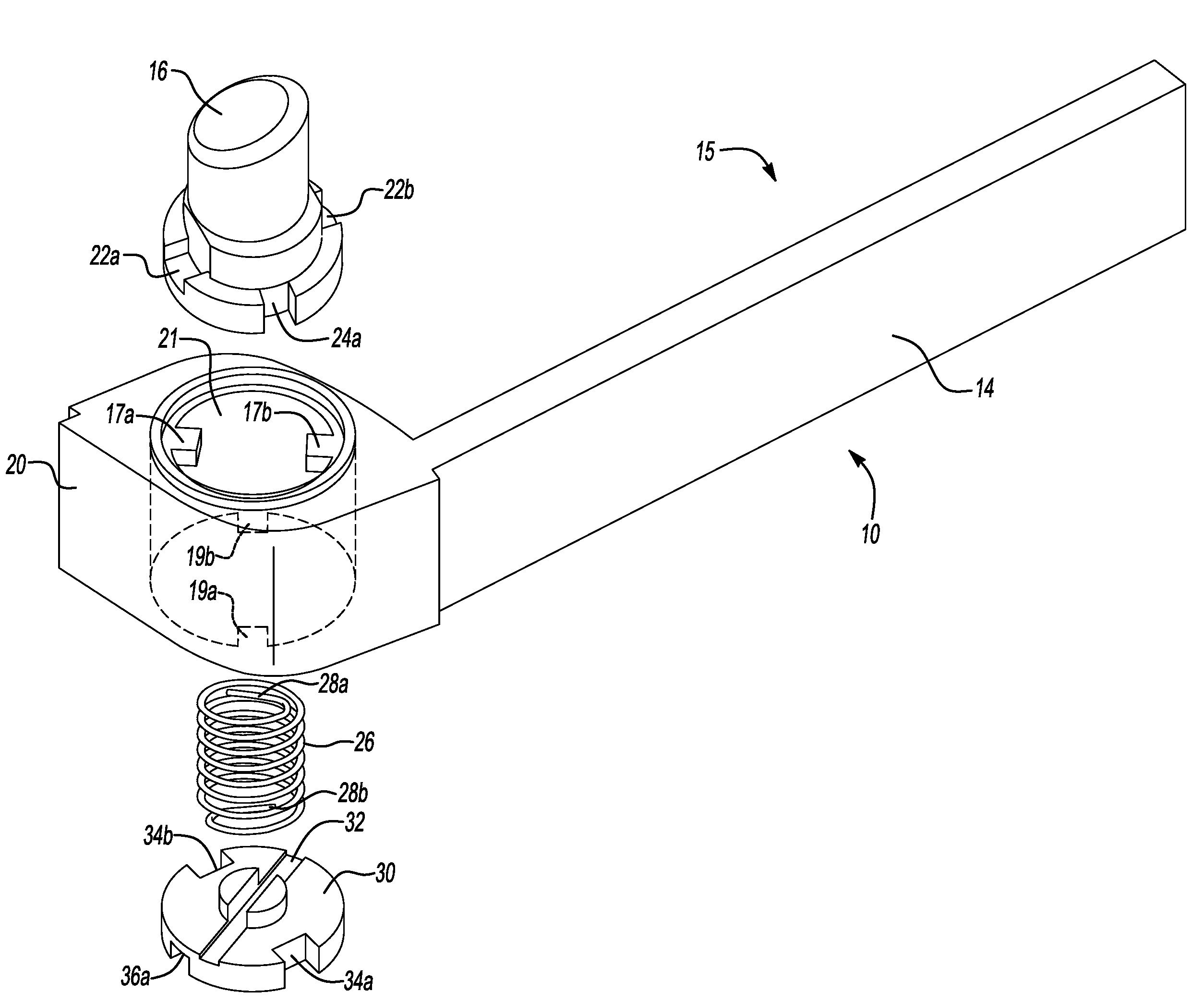
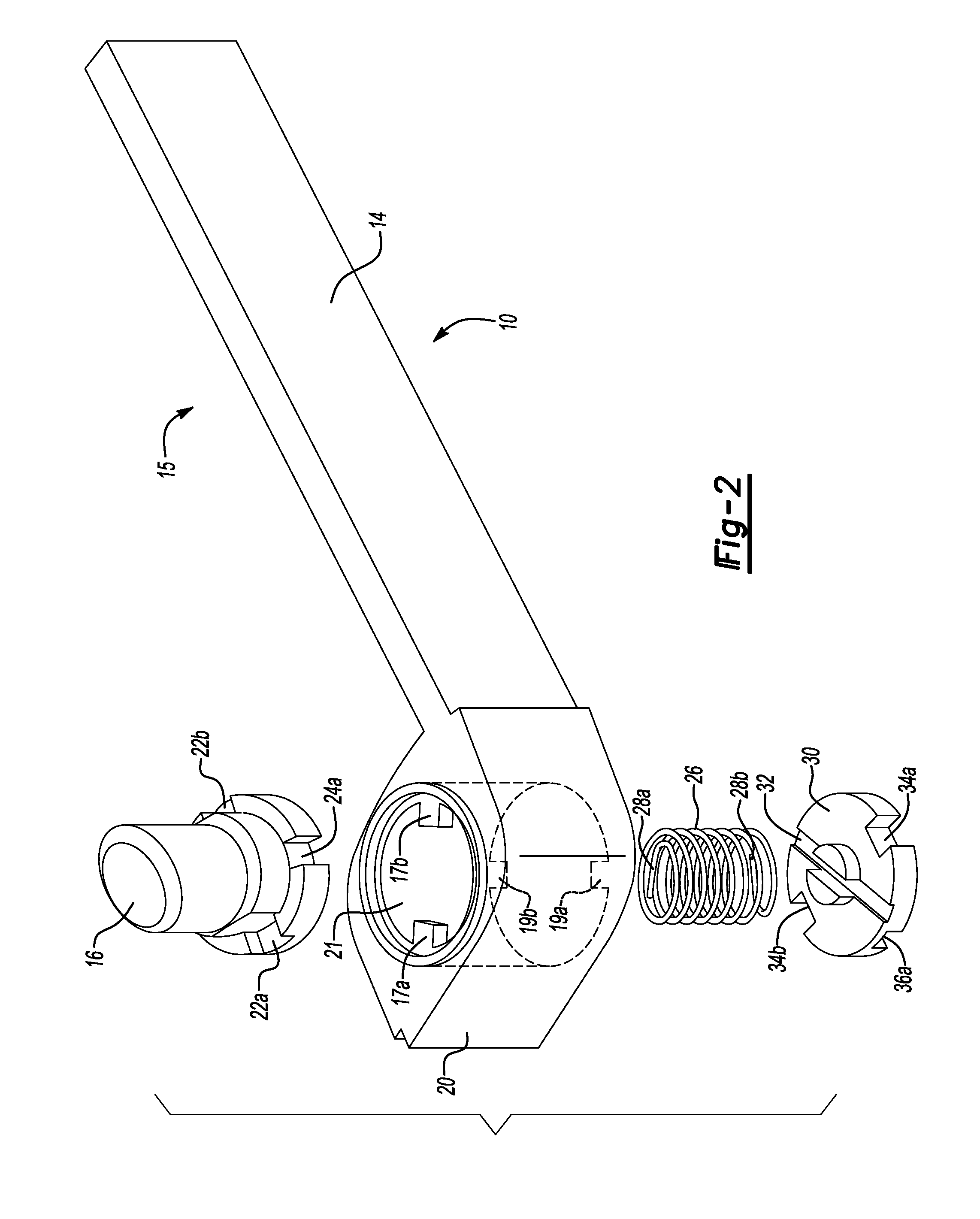
[0006]In at least one embodiment, a key fob assembly comprising a housing, a plurality of electrical components, a mechanical key, a spring cover, a spring, and a button is provided. The plurality of electrical components are positioned within the housing for transmitting radio frequency signals to a vehicle. The mechanical key includes a key holder for rotation to and from the housing. The key holder includes first and second ends positioned opposite to each other and the key holder defines an opening extending between the ends for defining a pivot axis to facilitate the rotational movement of the mechanical key. The spring cover is coupled to the key holder and positioned about the second end of the opening. The spring is positioned within the opening and is coupled to the spring cover. The button is coupled to the spring and is releasably coupled to the first end for preventing rotational movement of the key holder when the button is coupled to the first end and for facilitating rotational movement of the key holder about the pivot axis when the button is released from the key holder.
[0007]In another embodiment, a key fob assembly comprising a housing, a mechanical key, a spring cover, a spring, and a button is provided. The plurality of electrical components are positioned within the housing for transmitting radio frequency signals to a vehicle. The mechanical key includes a key holder for rotation to and from the housing. The key holder includes first and second ends positioned opposite to each other and the key holder defines an opening extending between the ends for defining a pivot axis to facilitate the rotational movement of the mechanical key. The spring cover is coupled to the key holder and positioned about the second end of the opening. The spring is positioned within the opening and is coupled to the spring cover. The button is coupled to the first end of the key holder and to the spring for preventing rotational movement of the key holder. The button is releasable from the key holder in response to a force and is linearly moveable from the first end to the second end to compress the spring such that the spring causes the key holder to rotate about the pivot axis for rotating the mechanical key.

Problems solved by technology

Vehicle designers have no option but to provide circular buttons which limit the design capability of the key fob.

Method used


Image

  • Rotation mechanism for key blade
  • Rotation mechanism for key blade
  • Rotation mechanism for key blade

Examples


Embodiment Construction

)

[0013]As required, detailed embodiments of the present invention are disclosed herein. However, it is to be understood that the disclosed embodiments are merely exemplary of the invention that may be embodied in various and alternative forms. The figures are not necessarily to scale, some features may be exaggerated or minimized to show details of particular components. Therefore, specific structural and functional details disclosed herein are not to be interpreted as limiting, but merely as a representative basis for the claims and / or as a representative basis for teaching one skilled in the art to variously employ the present invention.

[0014]Moreover, except where otherwise expressly indicated, all numerical quantities in this description and in the claims are to be understood as modified by the word “about” in describing the broader scope of this invention. Practice within any numerical limits stated is generally preferred. Also, unless expressly stated to the contrary, the desc...


PUM


Abstract

A key fob assembly for a vehicle that includes a housing is provided. A mechanical key includes a key holder for rotation to and from the housing. The key holder includes first and second ends positioned opposite to each other. The key holder defines an opening extending between the ends for defining a pivot axis to facilitate the rotational movement of the mechanical key. The spring cover is coupled to the key holder and positioned about the second end of the opening. The spring is positioned within the opening and is coupled to the spring cover. The button is coupled to the spring and is releasably coupled to the first end for preventing rotational movement of the key holder when the button is coupled to the first end and for facilitating rotational movement of the key holder about the pivot axis when the button is released from the key holder.

Description

BACKGROUND[0001]1. Technical Field[0002]The embodiments of the present invention generally relate to a remote keyless entry (RKE) fob having a rotatable key blade for a vehicle.[0003]2. Background Art[0004]A number of key fobs have been developed which include rotatable key blades. In one conventional approach, a user may manually grasp the key blade and rotate the key blade from out of a housing of the key fob in the event the key blade is needed to start an engine of the vehicle. In another conventional approach, the key fob may include a button which actuates one or more mechanisms for projecting the key blade from the housing of the key fob. The user may simply fold the key blade back into the housing of the key fob when it is necessary to stow the key blade when not in use.[0005]With the key fob configuration having the button for actuating the key blade, the shape of the button is limited to being circular such that the button is configured to rotate with the key blade as the ...

Claims


Application Information

Patent Timeline
IPC IPC(8): A44B15/00A47G29/10A45C11/32
CPCE05B19/043Y10T70/8676Y10T70/8757
Inventor LUO, YIZHONG, YUANLONG
Owner LEAR CORP
Learn More