
Expandable reverse shoulder trial

a shoulder joint and expansion technology, applied in the field of expansion shoulder joint trial, can solve the problems of dislocation of the joint, decrease the size and cost of the overall instrument set, etc., and achieve the effect of reducing patient exposure, reducing surgical time, and easing the reduction and dislocation of the shoulder join

Active Publication Date: 2009-08-27
HOWMEDICA OSTEONICS CORP
View PDF71 Cites 31 Cited by
  • Summary
  • Abstract
  • Description
  • Claims
  • Application Information

AI Technical Summary

Benefits of technology

The present invention is an expandable shoulder trial that allows for easier reduction and dislocation of a shoulder joint during trialing. The trial can be custom fitted to a patient after the joint has been reduced, which reduces the risk of soft or hard tissue injuries related to extreme forces required for reduction. The trial can be expanded and contracted repeatedly, making the process more efficient and healthy for the patient. The trial is designed to expand in discreet increments, allowing for optimal deltoid tension. The invention also includes an insert with a concave recess and a shaft with a helical groove for securely attaching the trial to the patient. The trial can be used in a one-step trialing technique, reducing surgical time and hospital costs.

Problems solved by technology

Preferably, the expandable trial also decreases the size and cost of the overall instrument set, since only one trial per glenosphere diameter is generally required.
Following ROM and joint stability analysis, the surgeon can easily collapse the trial back to the neutral position and simply dislocate the joint.

Method used


Image

  • Expandable reverse shoulder trial
  • Expandable reverse shoulder trial
  • Expandable reverse shoulder trial

Examples


Embodiment Construction

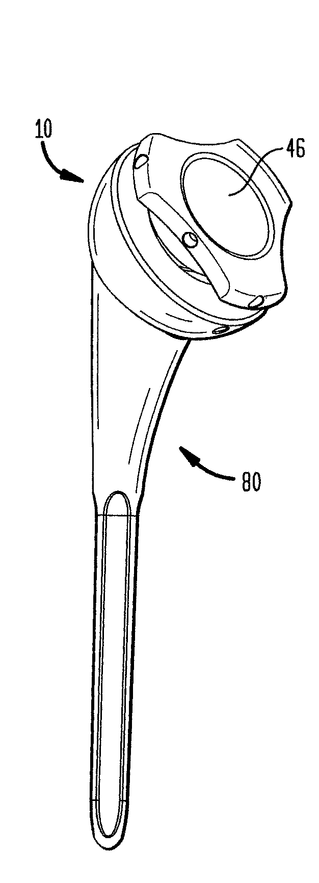
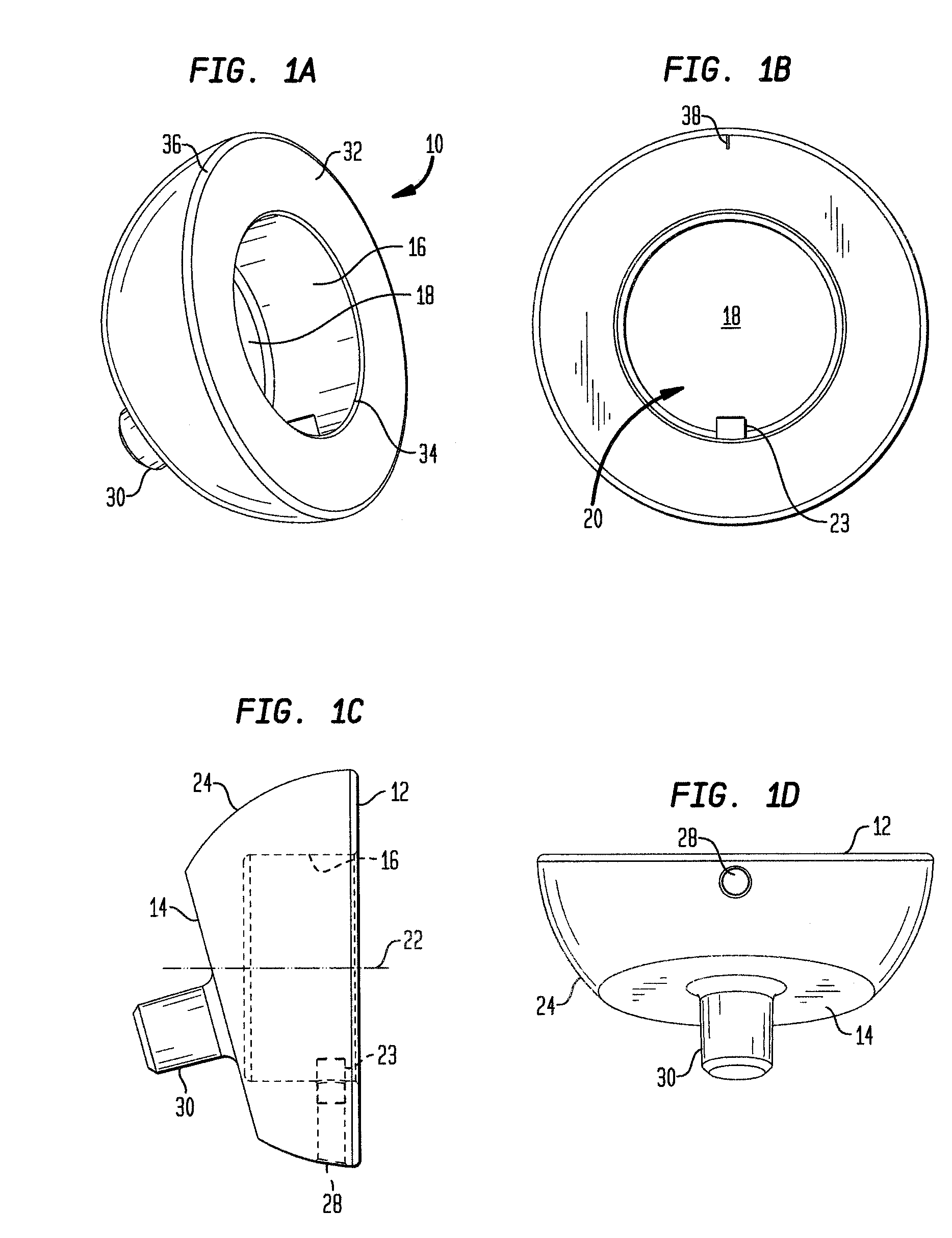
[0095]Referring to FIGS. 1A-1D, there is shown an embodiment of a humeral cup of the present invention designated generally by reference numeral 10. As shown in those figures, cup 10 includes a proximal end 12 and a distal end 14. Cup 10 preferably further includes a wall 16 and a base 18 defining a recess 20. Wall 16 is preferably circular, but may be other geometrical shapes such as octagonal or elliptical for example. Recess 20 defines a central axis 22 as shown in FIG. 1C. Preferably, a guide portion 23 protrudes from wall 16. Guide portion 23 is preferably configured as a pin.

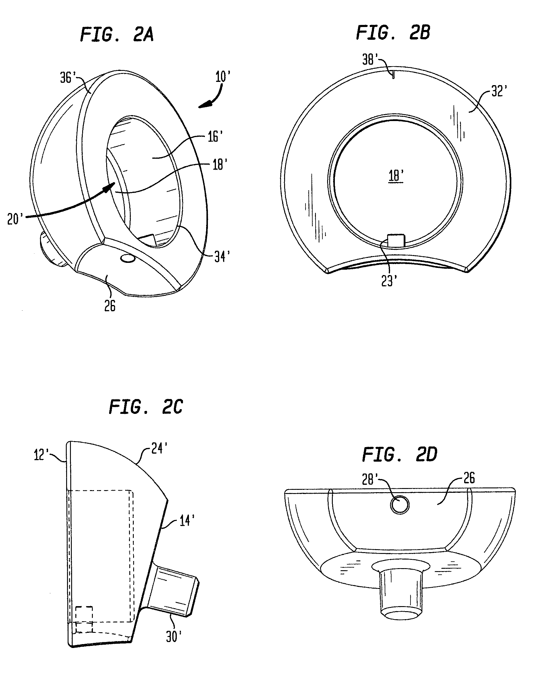
[0096]In the preferred embodiment, proximal end 12 and distal end 14 of cup 10 are not coplanar. Between distal end surface 14 and proximal end surface 12 is a hemispherical outer surface 24. In an alternative embodiment, as shown in FIGS. 2A-2D, a cup 10′ further includes a concave surface 26 located between a proximal end surface 12′ and a distal end surface 14′. Surface 26 faces medially and is preferab...


PUM


Abstract

An expandable shoulder trial for a reverse shoulder system is described. The trial includes a rotatably adjustable insert housed within a humeral cup. The insert has a proximal end and a distal end, the proximal end having a concave recess therein adapted to receive a glenosphere prosthesis. The distal end of the insert includes a shaft, the shaft having a helical groove disposed on at least a portion thereof. A distal end of the humeral cup is inserted in a humeral stem. The humeral cup has a proximal end including a recess therein, the recess defined by a circular wall. A guide pin protrudes from the circular wall and is adapted to engage the helical groove of the shaft of the insert. The proximal end of the insert may rotate along an axis toward the proximal end of the humeral cup and along the same axis away from the proximal end of the humeral cup.

Description

CROSS-REFERENCE TO RELATED APPLICATIONS[0001]This application is a continuation-in-part of U.S. application Ser. No. 11 / 974,424, filed on Oct. 12, 2007, the disclosure of which is incorporated herein by reference.FIELD OF THE TECHNOLOGY[0002]The present invention relates to an expandable reverse shoulder trial for reverse shoulder arthroplasty (RSA), and in particular it relates to such a trial including an expandable humeral cup configured to engage a rotatably adjustable insert.BACKGROUND OF THE INVENTION[0003]The successful outcome of RSA depends greatly on proper soft tissue tension. Since the rotator cuff is either absent or severely compromised and irreparable, the stability of the shoulder joint comes from significant deltoid tension holding the ball and socket joint together.[0004]Existing reverse shoulder systems require a surgeon to pick a trial liner and reduce the shoulder joint with that liner assembled into a humeral cup. If the correct liner is chosen, the soft tissue...

Claims


Application Information

Patent Timeline
Patent Type & Authority Applications(United States)
IPC IPC(8): A61F2/40
CPCA61F2/40A61F2250/0097A61F2/4684A61F2002/30331A61F2002/30332A61F2002/3042A61F2002/30507A61F2002/3055A61F2002/30553A61F2002/30594A61F2002/30617A61F2002/4022A61F2002/4037A61F2002/4044A61F2002/4085A61F2220/0025A61F2220/0033A61F2250/0007A61F2250/0008A61F2/4014
Inventor SPLIETH, ROY PHILIPLOREK, JAMES DAVID
Owner HOWMEDICA OSTEONICS CORP
Learn More