
Time and frequency domain based approaches for fine timing and frequency estimations in isdb-t and isdb-tsb receiver design

a time and frequency domain technology, applied in the field of communication systems, can solve the problems of large bit error rate and performance degradation, phase rotation of scatter pilots is generally not a good indicator of frequency and timing offset, and large bit error ra

Inactive Publication Date: 2009-08-27
ATMEL CORP
View PDF2 Cites 29 Cited by
  • Summary
  • Abstract
  • Description
  • Claims
  • Application Information

AI Technical Summary

Benefits of technology

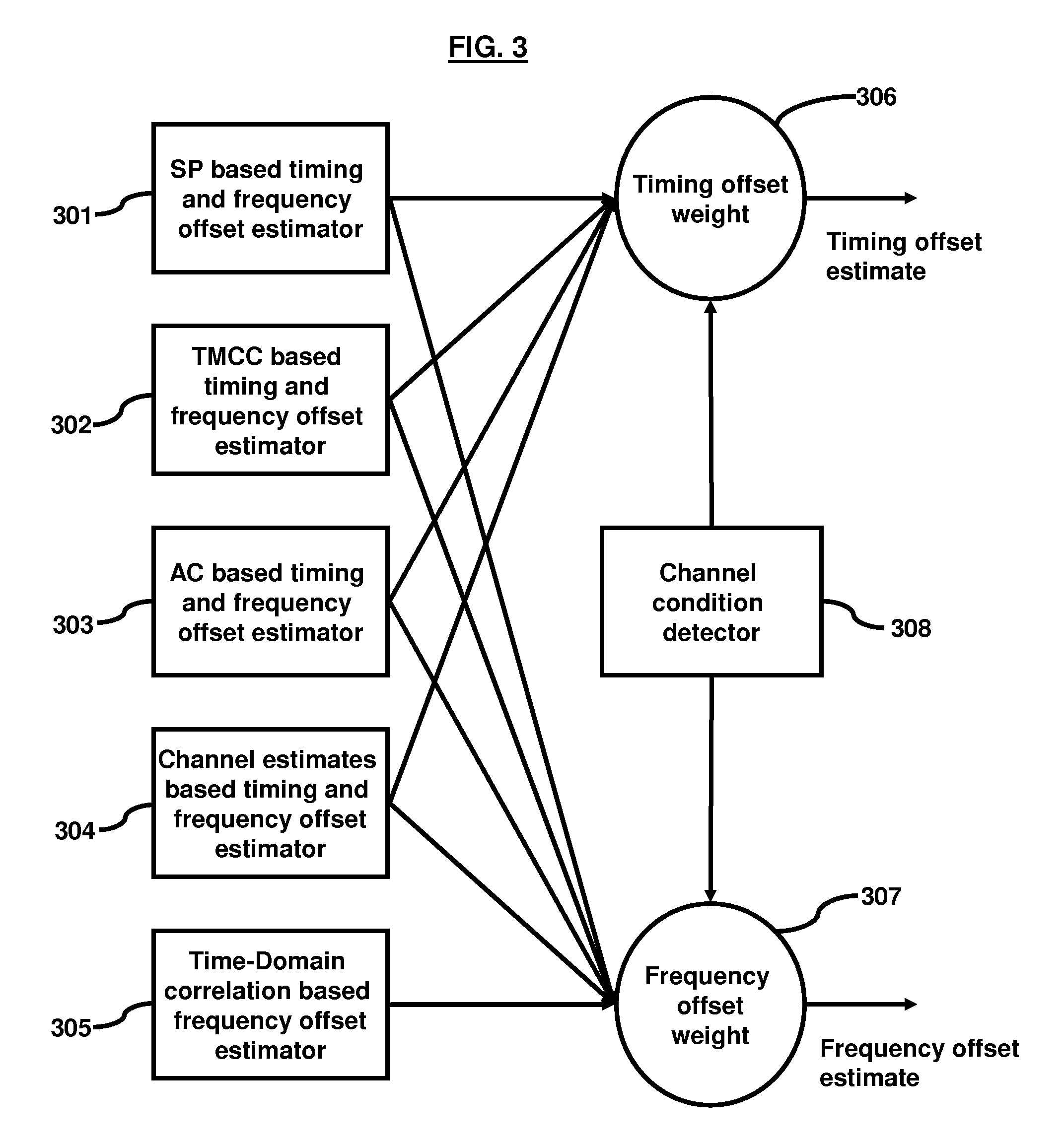
[0008]In view of the foregoing, the embodiments herein provide a method of timing and frequency offset estimation for a channel in an OFDM system, and a program storage device readable by computer, tangibly embodying a program of instructions executable by the computer to perform the method of timing and frequency offset estimation for a

Problems solved by technology

In conventional OFDM systems, timing and frequency offsets can cause large bit error rate and performance degradation.
As the scatter pilots include a portion of channel changes, the phase rotation of the scatter pilots is generally not a good indicator of the frequency and timing offsets.
As seen, with the increase in the rate of changes in the channel, the estimations of the timing and frequency offsets deteriorate considerably resulting in large bit error rates and poor system performance.

Method used


Image

  • Time and frequency domain based approaches for fine timing and frequency estimations in isdb-t and isdb-tsb receiver design
  • Time and frequency domain based approaches for fine timing and frequency estimations in isdb-t and isdb-tsb receiver design
  • Time and frequency domain based approaches for fine timing and frequency estimations in isdb-t and isdb-tsb receiver design

Examples


first embodiment

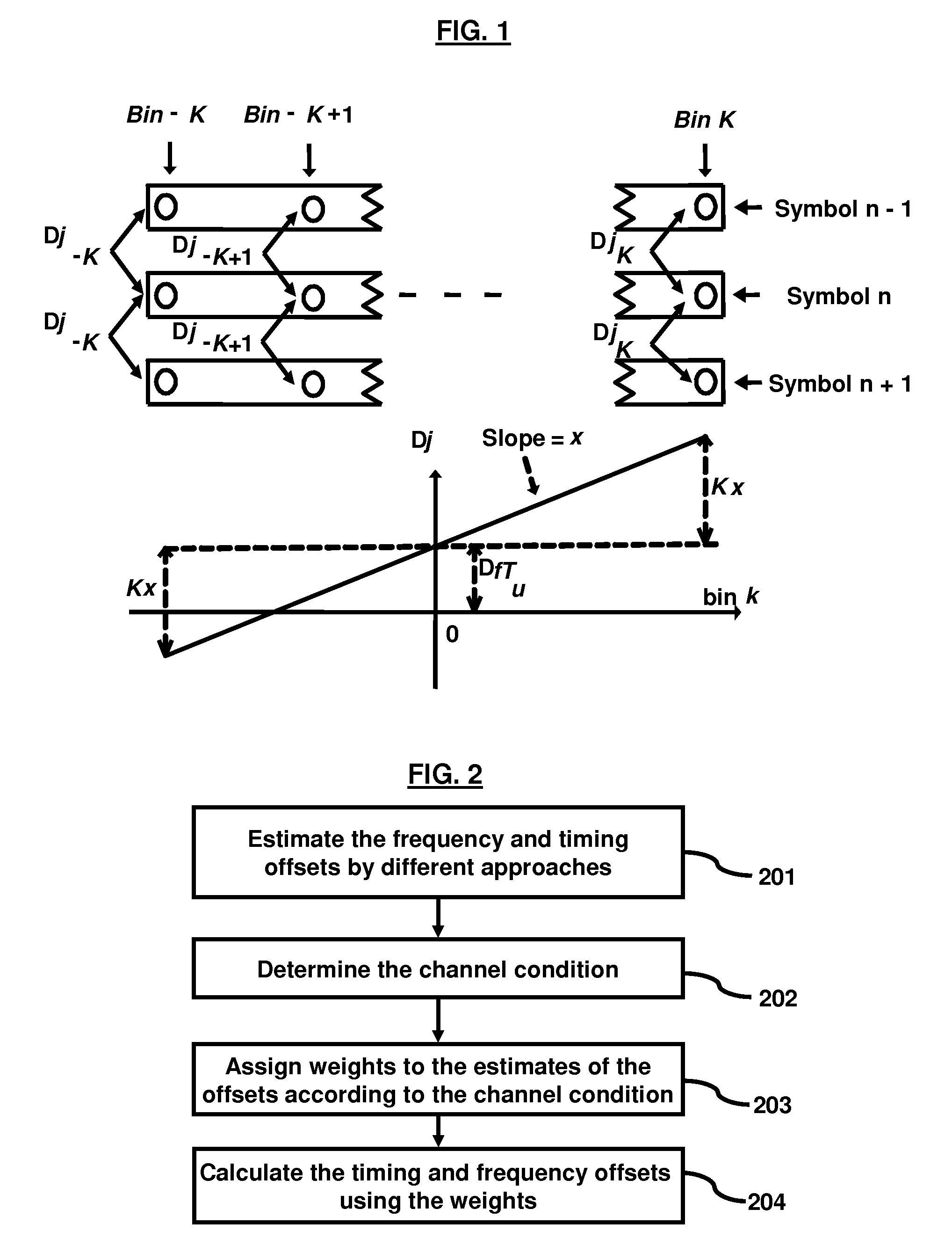
[0036]The estimator based on TMCC 302 uses phase rotation on TMCC sub-carriers to estimate frequency and timing offsets, wherein the TMCC sub-carriers are placed continuously in ISDB-T and ISDB-TSB channels. FIG. 6 shows how the phase difference of the TMCC bins is taken. FIG. 7, with reference to FIG. 3, is a flow diagram illustrating a method of frequency and timing offset herein. The phase difference of a TMCC bin over two adjacent symbols is approximated (701) as:

Δφk≈ΔfTu+ξk+Phtmcc   (3)

where Phtmcc reflects TMCC data modulated on TMCC bins. After TMCC information is locked (702) for each symbol, the modulated TMCC data, Phtmcc is subtracted (703) from equation (3). TMCC information is preferably locked first to learn the information bit on the TMCC bins, so after subtracting modulated TMCC data, Phtmcc, the phase difference between two symbols reflects the channel phases. After removing the modulated TMCC data, Phtmcc from equation (3), the frequency offset is calculated (704)...

second embodiment

[0037]The offset estimator based on the AC 303 uses a phase rotation on AC sub-carriers to estimate frequency and timing offsets, wherein the AC sub-carriers are placed continuously in ISDB-T and ISDB-TSB channels. FIG. 8, with reference to FIG. 3, is a flow diagram illustrating a method of frequency and timing offset herein. The phase difference of an AC bin over two adjacent symbols is approximated (801) as:

Δφk≈ΔfTu+ξk+Phac   (4)

where Phac reflects AC data modulated on AC bins. In ISDB-T and ISDB-TSB, Phac is either 0 radian or Π radians, which depends on the value of phase difference, Δφk. If (802) −Π / 2≦Δφkac is estimated (803) as 0 radian (Yes); else (No) Phac is estimated (804) as Π radians. Phac is subtracted (805) from equation (4) so that the phase difference, Δφk between two symbols reflects the channel phases. After removing the modulated AC data, Phac from equation (4), the mean and slope of the phase difference is calculated (806) and then the frequency and timing offse...

third embodiment

[0038]FIG. 9, with reference to FIG. 3, is a flow diagram illustrating a method of frequency and timing offset herein. The offset estimator based on the channel estimates 304 uses scatter pilots to interpolate channel estimates on each sub-carrier. The phase difference on the channel estimate on each sub-carrier over two adjacent symbols is calculated (901). The mean and slope of the phase difference is calculated (902). The mean of the phase difference indicates (903) the frequency offset and the slope of the phase difference is the timing offset.


PUM


Abstract

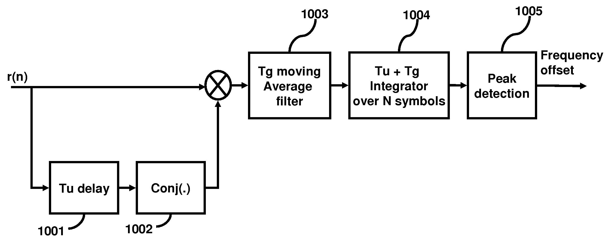
A method and apparatus for estimating timing and frequency offsets in an ISDB-T and ISDB-TSB receiver. In different embodiments, the method comprises estimating timing and frequency offsets by different estimation processes; assigning weights to the timing and frequency offsets according to the channel condition; and calculating timing and frequency offsets using the estimates of timing and frequency offsets and the weights.

Description

BACKGROUND[0001]1. Technical Field[0002]The embodiments herein generally relate to communication systems, and more particularly to the field of orthogonal frequency division multiplexing (OFDM) communication systems.[0003]2. Description of the Related Art[0004]In conventional OFDM systems, timing and frequency offsets can cause large bit error rate and performance degradation. Timing offset refers to a delay in the received signal relative to the expected signal from the transmitter. Frequency offset refers to the difference between the frequency of a source and a reference frequency.[0005]In a pilot based OFDM system, a traditional method for fine timing and frequency offset estimation is to detect the sub-carrier phase rotation on pilot bins across symbols. The mean phase rotation would indicate the fine frequency offset while the slope of phase rotation across the pilots would indicate the fine timing offset. In ISDB-T and ISDB-TSB, the pilots (referred to as scatter pilots) are ...

Claims


Application Information

Patent Timeline
IPC IPC(8): H04L27/28
CPCH04L25/0204H04L25/0224H04L25/0232H04L27/2695H04L27/2662H04L27/2675H04L27/2676H04L27/2657
Inventor GU, YONGRUMA, JUN
Owner ATMEL CORP
Learn More