Apparatus and method for adjustable variable transmissivity polarized eye glasses
a technology of polarized eye glasses and glasses, applied in the field of glasses and glasses, can solve the problem of low transmittance of the lens
- Summary
- Abstract
- Description
- Claims
- Application Information
AI Technical Summary
Benefits of technology
Problems solved by technology
Method used
Image
Examples
first embodiment
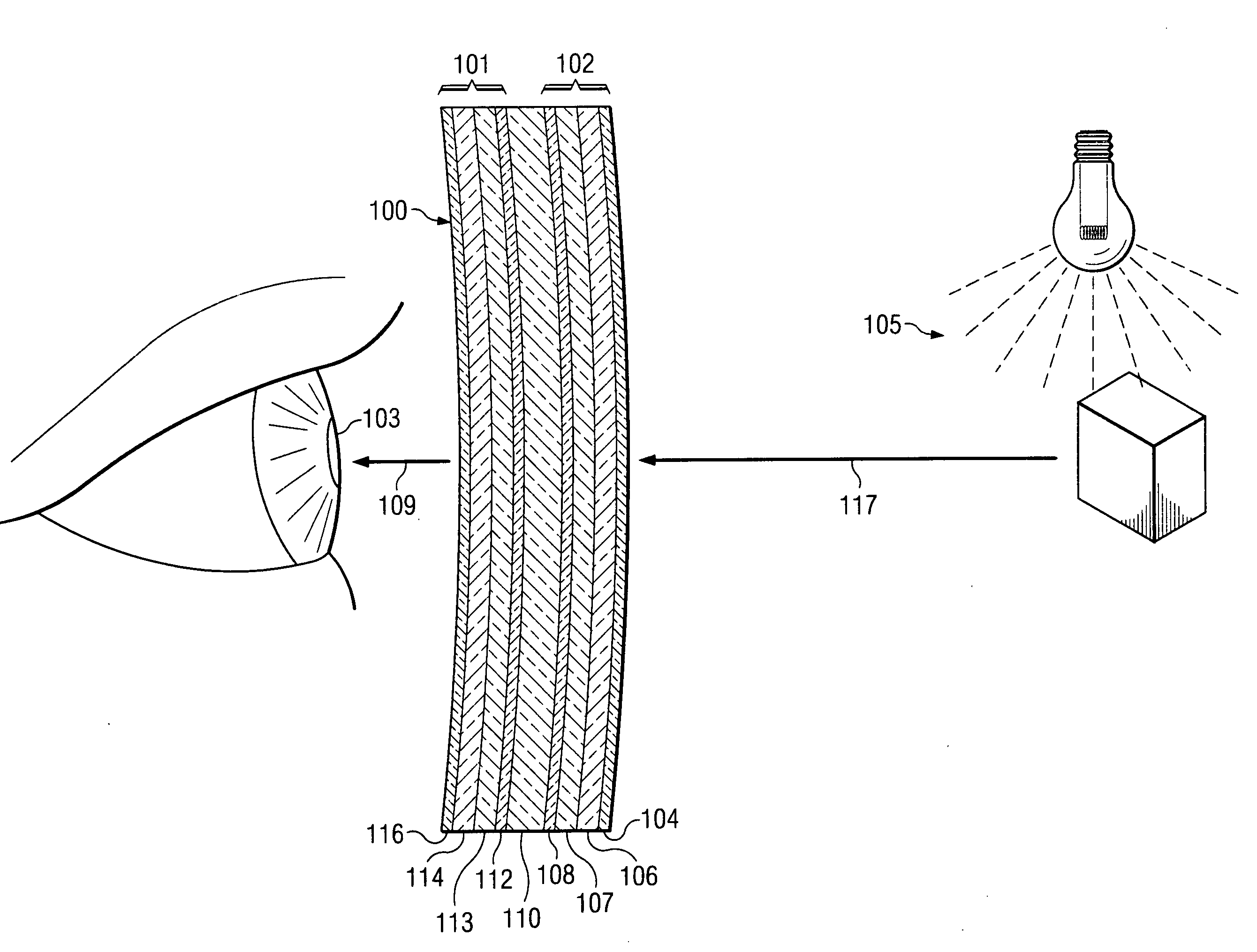
[0055]FIG. 6 is a block diagram of a first embodiment electronic circuit 200. Electronic circuit 200 provides electronic control of the transmissivity of lens element 218 allowing for a certain fraction of incident light 201 to fall on a wearer's eye 219 and is comprised of a dc / dc boost converter 221 connected to a battery 220; a light sensor 202; an amplifier 204 connected to light sensor 202, the amplifier 204 having gain control 205 and bias control 206; a pulse width modulator 210 connected to amplifier 204; an oscillator 211 driving the frequency and timing of the pulse width modulator 210; a buffer amplifier 214 connected to lens element 218 for conditioning a drive signal 216 to drive lens element 218, the input of buffer amplifier 214 connected to pulse width modulator 210 and generating PWM signal 212. Incident light 201 which is directly from the ambient, falls on light sensor 202 where the detected light quanta are converted to a photocurrent 203. Photocurrent 203 is sen...
second embodiment
[0056]FIG. 7 is a block diagram of a second embodiment electronic circuit 240. Electronic circuit 240 provides electronic control of the transmissivity of lens element 242 allowing for a certain fraction of incident light 241 to fall on a wearer's eye 243 and is comprised of a light sensor 244 generating photocurrent 234; an integrating transimpedance amplifier 245 connected to light sensor 244 having sensitivity control 246 and an output photovoltage signal 235 proportional to photocurrent 234. Electronic circuit 240 further comprises a comparator 247 with voltage reference 253; a charging circuit 250 connected to capacitor 251 for charging a capacitor 251 having peak voltage reference 248, a voltage follower 254 connected to capacitor 251 and charging circuit 250; a pulse width modulator circuit 256 connected to the output of voltage follower 254 and driven by an oscillator 255, and a buffer amplifier 258 connected to PWM circuit 256 and to lens element 242 for driving lens elemen...
third embodiment
[0059]FIG. 8 is a block diagram of a third embodiment electronic circuit 260. Electronic circuit 260 provides electronic control of the transmissivity of lens element 282 allowing for a certain fraction of incident light 262 to fall on a wearer's eye 280 and is comprised of a DC / DC converter 265 connected to battery 266 and having output DC voltage Vcc 259 for powering the components of circuit 260; a light sensor 261 for sensing incident light 262; a crystal oscillator 267 oscillating at frequency f1; a square wave oscillator 283 oscillating at frequency f2 producing square wave signal 287 connected to a microprocessor 268 and an AND gate 284; microprocessor 268 having an A / D converter 264 connected to light sensor 261 and a timer 263 connected to crystal oscillator 267, microprocessor 268 further having memory 269 which contains program instructions 285 for operation and for generating a pulse width modulated signal; and a serial interface 271 for communications with microprocesso...
PUM
| Property | Measurement | Unit |
|---|---|---|
| luminance | aaaaa | aaaaa |
| luminance | aaaaa | aaaaa |
| angle | aaaaa | aaaaa |
Abstract
Description
Claims
Application Information
 - R&D
- Intellectual Property
- Life Sciences
- Materials
- Tech Scout
- Unparalleled Data Quality
- Higher Quality Content
- 60% Fewer Hallucinations
Browse by: Latest US Patents, China's latest patents, Technical Efficacy Thesaurus, Application Domain, Technology Topic, Popular Technical Reports.
© 2025 PatSnap. All rights reserved.Legal|Privacy policy|Modern Slavery Act Transparency Statement|Sitemap|About US| Contact US: help@patsnap.com


