Planar light source device and liquid crystal display device
a light source device and liquid crystal display technology, applied in the direction of planar/plate-like light guides, instruments, electromagnetic radiation sensing, etc., can solve the problems of large optical output, difficult to form compact backlights led backlights not becoming familiar for large display use, etc., to achieve the effect of simple configuration
- Summary
- Abstract
- Description
- Claims
- Application Information
AI Technical Summary
Benefits of technology
Problems solved by technology
Method used
Image
Examples
embodiment 1
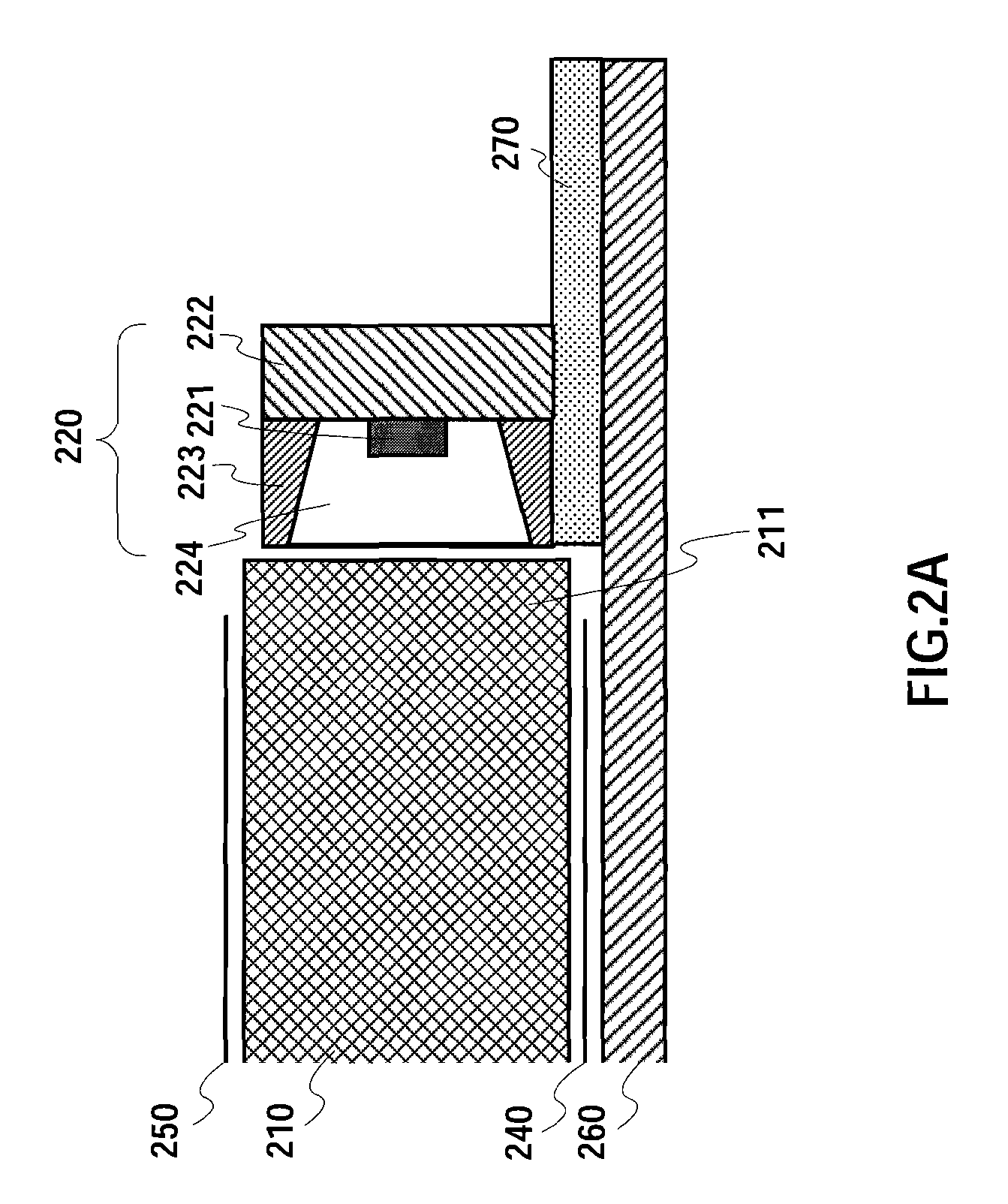
[0034]FIG. 3 is a perspective view showing the configuration of the planar light source apparatus according to Embodiment 1 of the present invention. In FIG. 3, planar light source apparatus 300 is constituted by light guide plate 310, laser light source 320, scanning mirror 330, reflecting sheet 340 and control circuit 350. Planar light source apparatus 300 regularly makes a light flux forming a beam from laser light source 320 scan with scanning mirror 330 constituting an optical scanning system, and make the light incident to the incident face provided in a corner part of light guide plate 310. A linear illuminating light is instantaneously formed by an incident light flux, that is, incident light, and the linear illumination light moves according to the scanning of the mirror. The range of scanning angle and the shape of the incident face are adjusted so as to cover the whole of the light guide plate in one cycle.
[0035]Light guide plate 310, is virtually flat, where one of the o...
embodiment 2
[0059]With Embodiment 1, the incident face of the light guide plate is at a corner part of the light guide plate. However, as shown in FIG. 7, it is also possible to place laser light source 420 and scanning mirror 430 in the rear face of light guide plate 410, reflect incident light at folded mirror 450 and input to incident light from an whole of a side face part of light guide plate 410. 440 is a reflection sheet.
[0060]In this case, although the scanning square measure function S(t) is different from the case in FIG. 6, the brightness of the whole of the display is made uniform by applying light intensity modulation proportional to time derivative of the scanning square measure S “dS / dt” to the optical output P(t).
[0061]According to the present embodiment, laser light source 420 is placed under light guide plate 410, so that it is possible to improve the device design flexibly. Moreover, the incident face or scanning mirror 430 is not placed at the corner part of light guide plat...
PUM
| Property | Measurement | Unit |
|---|---|---|
| light intensity | aaaaa | aaaaa |
| time rate of change | aaaaa | aaaaa |
| density | aaaaa | aaaaa |
Abstract
Description
Claims
Application Information
 - R&D
- Intellectual Property
- Life Sciences
- Materials
- Tech Scout
- Unparalleled Data Quality
- Higher Quality Content
- 60% Fewer Hallucinations
Browse by: Latest US Patents, China's latest patents, Technical Efficacy Thesaurus, Application Domain, Technology Topic, Popular Technical Reports.
© 2025 PatSnap. All rights reserved.Legal|Privacy policy|Modern Slavery Act Transparency Statement|Sitemap|About US| Contact US: help@patsnap.com


