Liquid injecting head, method of manufacturing liquid injecting head, and liquid injecting apparatus

a technology of liquid injection head and manufacturing method, which is applied in printing and other directions, can solve the problems of air bubbles missing, inability to shorten the gap between adjacent supply bodies, and increase the size of the head, so as to reduce the area of the filter, shorten the gap between adjacent supply bodies, and increase the effect of effective area of the filter

Active Publication Date: 2009-08-20
SEIKO EPSON CORP
View PDF6 Cites 13 Cited by
  • Summary
  • Abstract
  • Description
  • Claims
  • Application Information

AI Technical Summary

Benefits of technology

[0020]In the above-described liquid injecting head, by fixing the first supply member, the filter, and the second supply member to be integrated by using the bonding resin that is formed in the concave parts, the areas for individually welding the filter to the first supply member and the second supply member are not needed. Accordingly, an effective area of the filter is increased, and a gap between adjacent supply bodies can be shortened. As a result, the head can be miniaturized. In addition, the area of the filter does not need to be decreased for miniaturizing the head. In addition, an increase in the dynamic pressure can be prevented, and accordingly, the driving voltage that is used for driving the pressure generating unit such as a piezoelectricity element or a heating element is not need to be raised. Furthermore, generation of a gap between the first supply member and the second supply member can be prevented assuredly by using the bonding resin, and accordingly, leakage of the liquid from the gap can be prevented assuredly.

Problems solved by technology

In the ink-jet record heads, there is a problem that injection defect such as dot missing due to the air bubbles occurs in a case where air bubbles contained in the ink of the ink cartridge or air bubbles mixed into the ink at a time when the ink cartridge is attached or detached are supplied to the head main body.
In addition, since areas for individually welding the ink supplying needle and the filter to the supply member are needed, a gap between adjacent ink supplying needles cannot be shortened.
As a result, there is a problem that the size of the head is increased.
Accordingly, there is a problem that a driving voltage that is used for driving a pressure generating unit such as a piezoelectric element or a heating element is needed to be increased.
In addition, when the ink supplying needle and the supply member are fixed by a heat welding process, a gap therebetween may be generated.
In such a case, there is a problem that ink leaks from the gap.
Furthermore, when the filter and the ink supplying needle are individually fixed to the supply member, there is a problem that the manufacturing cost increases.
Such problems exist not only in the ink-jet record head but also in a liquid injecting head that injects a liquid other than the ink.

Method used


Image

  • Liquid injecting head, method of manufacturing liquid injecting head, and liquid injecting apparatus
  • Liquid injecting head, method of manufacturing liquid injecting head, and liquid injecting apparatus
  • Liquid injecting head, method of manufacturing liquid injecting head, and liquid injecting apparatus

Examples


embodiment 1

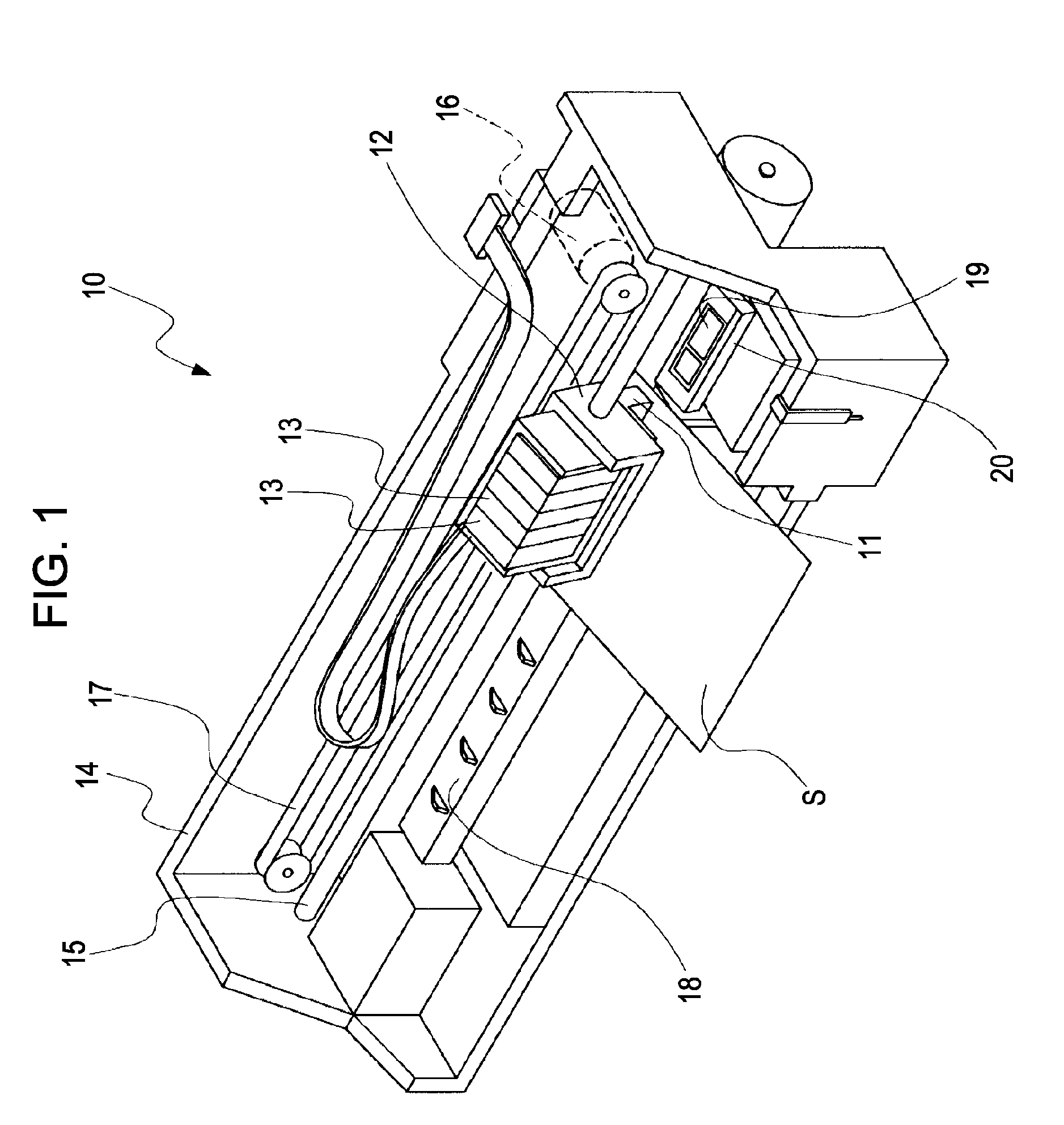
[0034]FIG. 1 is a schematic perspective view of an ink jet recording apparatus as an example of a liquid injecting apparatus according to Embodiment 1 of the invention. In the ink jet recording apparatus 10, as shown in FIG. 1, an ink-jet record head (hereinafter, also referred to as a record head) 11 as an example of a liquid injecting head that injects ink droplets is fixed to a carriage 12. To this record head 11, ink cartridges 13 as liquid storing units in which ink of a plurality of different colors such as a black color (B), a light black color (LB), a cyan color (C), a magenta color (M), and a yellow color (Y) is stored are detachably fixed.

[0035]The carriage 12 in which the record head 11 is mounted is installed to a carriage shaft 15 that is installed to an apparatus main body 14 to be movable in the direction of the shaft. By transferring the driving force of a driving motor 16 to the carriage 12 through a plurality of gears not shown in the figure and a timing belt 17, t...

embodiment 2

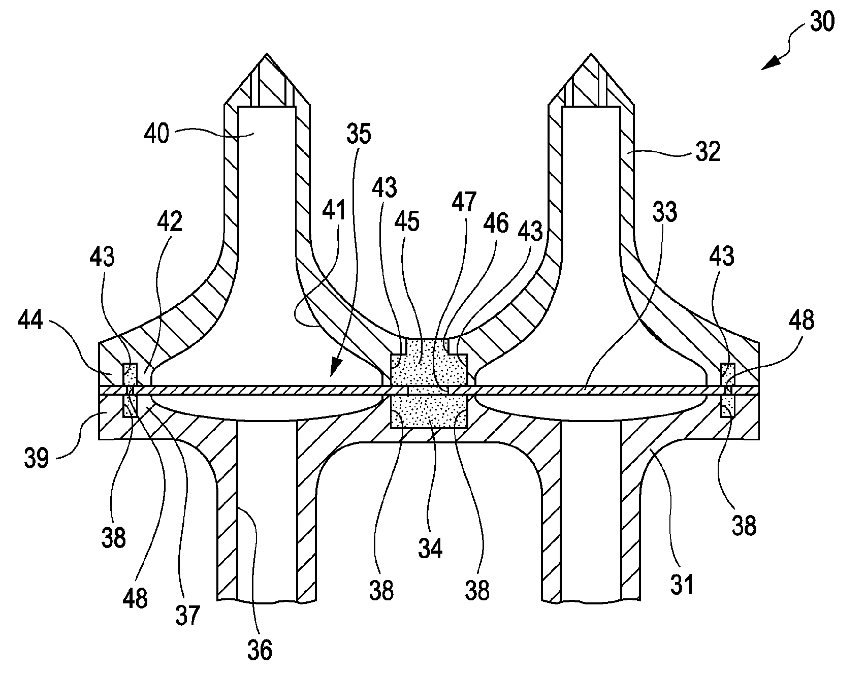
[0080]FIG. 10 shows a cross-section view of a supply member according to Embodiment 2 of the invention. The supply member 30A according to this embodiment is the same as that according to Embodiment 1 except that fine holes 501 and 502 that become air extracting holes at a time when the supply member main body 31A and the supply needle 32A shape the bonding resin 34. Thus, to each same part as that of Embodiment 1, a same reference sign is assigned, and a duplicate description thereof is omitted here.

[0081]The fine hole 501 is formed to perforate from the bottom part of the concave part 38 of the supply member main body 31A to the surface of the supply member main body 31 that is located on a side opposite to the filter 33. In addition, the fine hole 502 is formed to perforate from the bottom part of the concave part 43 of the supply needle 32 to the surface of the supply needle 32A that is located on a side opposite to the filter 33. The fine holes 501 and 502 become air extracting...

embodiment 3

[0083]FIG. 11 shows a cross-section view of a supply member according to Embodiment 3 of the invention. The supply member 30B according to this embodiment is the same as that according to Embodiment 1 except that an outer part 510 is included. Thus, to each same part as that of Embodiment 1, a same reference sign is assigned, and a duplicate description thereof is omitted here.

[0084]The outer part 510 is formed of a resin that is integrally formed on the outer circumference of the supply member main body 31 and the supply needle 32. The outer part 510 is integrally formed with the bonding resin 34, simultaneously. However, the outer part 510 may be molded by a separate process. By disposing the outer part 510, the outer part 510 is formed by also breaking into a gap between the supply member main body 31 and the supply needle 32 in which the filter 33 is not disposed. Accordingly, an advantage that the outer circumferences of the supply member main body 31, the supply needle 32, and...


PUM


Abstract

A liquid injecting head includes a first supply member and a second supply member in which the liquid supplying path is formed and a filter that is pinched by the first supply member and the second supply member and is disposed in correspondence with the liquid supplying path. In areas that surround the liquid supplying path of the first supply member and the second supply member on the filter side and face each other, filter pinching parts that are brought into contact with the filter are included and concave parts that surround the filter pinching parts are included on the outer side of the filter pinching parts. In addition, the first supply member, the filter, and the second supply member are bonded together by a bonding resin that is formed by flowing into the concave parts of the first supply member and the second supply member

Description

BACKGROUND[0001]1. Technical Field[0002]The present invention relates to a liquid injecting head that injects a liquid, a method of manufacturing the liquid injecting head, and a liquid injecting apparatus including the liquid injecting head, and more particularly, to an ink-jet record head that injects ink as the liquid, a method of manufacturing the ink-jet record head, and an ink jet recording apparatus[0003]2. Related Art[0004]In ink-jet record heads that are major examples of the liquid injecting heads, generally, ink is supplied to a head main body from an ink cartridge that is a liquid storing unit in which ink fills through an ink flowing path that is formed in an ink supplying needle that is an ink supplying body detachably inserted into the ink cartridge and a supply member such as a cartridge case in which the ink cartridge is held. In addition, by driving a pressure generating unit such as a piezoelectric element that is installed to the head main body, the ink supplied ...

Claims


Application Information

Patent Timeline
Patent Type & Authority Applications(United States)
IPC IPC(8): B41J2/175
CPCB41J2/17563
Inventor KAMIKURA, HIROYUKI
Owner SEIKO EPSON CORP
Why Eureka
Try Eureka