Liquid ejection head, method for manufactuirng the same, and liquid ejecting apparatus

a liquid ejection and liquid ejection technology, which is applied in the direction of adhesive processes, adhesive processes with surface pretreatment, printing, etc., can solve the problems of air trapped in the ink, difficult to reduce the interval between the ink supply needles, and failure of ejection, so as to reduce the interval between the suppliers and increase the driving voltage of the piezoelectric element, the effect of increasing the effective area of the filter

Inactive Publication Date: 2009-09-10
SEIKO EPSON CORP
View PDF31 Cites 21 Cited by
  • Summary
  • Abstract
  • Description
  • Claims
  • Application Information

AI Technical Summary

Benefits of technology

[0014]The first and the second supply member and the joining portion of the filter are joined into one body with the resin joint. Thus, no region is required for welding the filter to the first supply member and the second supply member. Consequently, the effective area of the filter can be increased and the interval between the suppliers can be reduced. In addition, since the resin penetrating the joining portion between the flow channels seals the filter portions, the liquid ejection head can be miniaturized without mixing the liquids running through the plurality of flow channels even though the filter extends across the plurality of flow channels. In addition, it is not required that the effective area of the filter be reduced to miniaturize the head. It is accordingly not required that the driving voltage of the piezoelectric element be increased while the dynamic pressure is prevented from increasing. Furthermore, since the resin penetrates the joining portion of the filter, the regions between the liquid supply channels can be reliably sealed to prevent liquids from leaking between the flow channels.
[0023]Preferably, either the first supply member or the second supply member has a filling hole in a region thereof corresponding to the joining portion. The resin is introduced through the filling hole. The mold has a cavity surrounding the joining portion and a gate communicating with the cavity. Thus, the resin introduced from the gate through the filling hole can more easily penetrate the joining portion and thus more reliably seals the region between the liquid supply channels. Consequently, the liquids can be prevented from leaking between the flow channels with reliability.

Problems solved by technology

However, the cartridge contains air with the ink, and when the cartridge is removed from or attached to the head, air may be trapped in the ink.
Such air can be delivered to the head body and undesirably cause ejection failure such as dot missing.
It is therefore difficult to reduce the intervals between the ink supply needles, and accordingly the head becomes large.
In addition, if the area of the filter is excessively reduced to miniaturize the head having the structure disclosed in the above cited patent document, the driving voltage for driving the pressure generator, such as a piezoelectric element or a heating element, must be increased undesirably because of the increase of dynamic pressure.
In the structure in which the ink supply needle and the supply member are fixed by, for example, thermal welding, a gap may be formed between the ink supply needle and the supply member, and thus the ink may leak from the gap.
The structure in which the filter and the ink supply needle are fixed to the supply member in different process steps leads to an increased cost.
However, liquids running through the plurality of flow channels may be undesirably mixed.
These problems can arise not only in the ink jet recording head, but also in the liquid ejection head ejecting liquid other than ink.

Method used


Image

  • Liquid ejection head, method for manufactuirng the same, and liquid ejecting apparatus
  • Liquid ejection head, method for manufactuirng the same, and liquid ejecting apparatus
  • Liquid ejection head, method for manufactuirng the same, and liquid ejecting apparatus

Examples


first embodiment

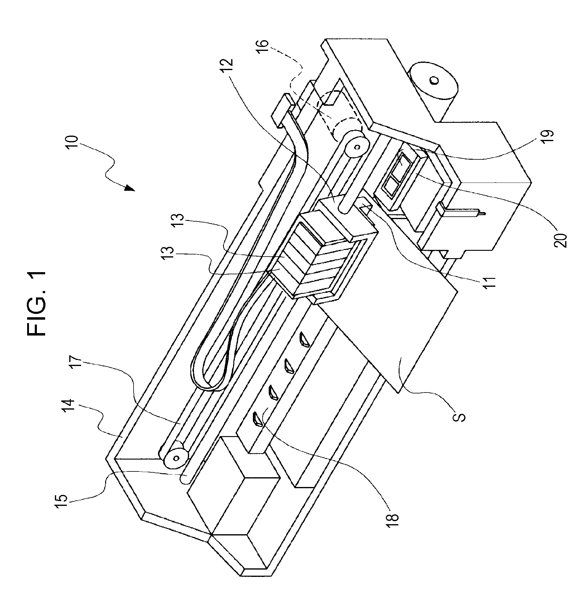
[0037]FIG. 1 is a schematic perspective view of an ink jet recording apparatus, which is a type of the liquid ejecting apparatus according to the first embodiment of the invention. The ink jet recording apparatus 10 of the first embodiment includes an ink jet recording head (hereinafter may be referred to as the recording head) 11 that is a liquid ejection head ejecting ink droplets. The recording head 11 is fixed to a carriage 12, and to which ink cartridges 13, or liquid reservoirs, are removably secured, as shown in FIG. 1. The ink cartridges 13 respectively contain a plurality of colors including black (B), light black (LB), cyan (C), magenta (M), and yellow (Y).

[0038]The carriage 12 having the recording head 11 is secured to a carriage shaft 15 fixed to the device body 14 and is movable along the shaft. The carriage 12 is moved along the carriage shaft 15 by transmitting the driving force from a driving motor 16 to the carriage 12 with a plurality of gears (not shown) and a tim...

second embodiment

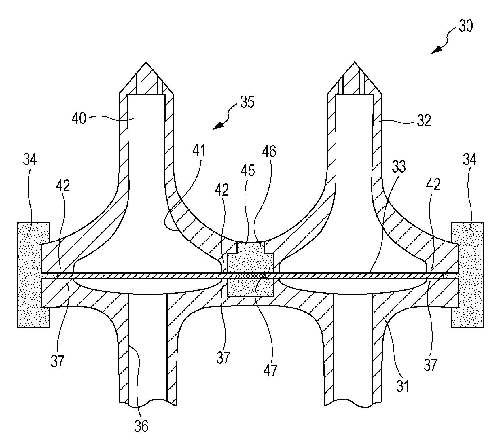
[0083]FIG. 10 is a sectional view of a supply member according to a second embodiment. The supply member 30A of the second embodiment has the same structure as in the first embodiment, except that the outer region of the filter 33 slightly protrudes into the outer portions 34. The same parts as in the first embodiment are designated by the same reference numerals and the descriptions will not be repeated.

[0084]As shown in FIG. 10, the filter 33A is slightly larger than the outer diameters of the filter holding portions 37 and 42 of the supply member body 31A and the supply needles 32, and the outer region of the filter 33A is held by the outer portion 34A. The outer region from the filter holding portion 37 of the supply member body 31A and the outer region from the filter holding portion 42 of the supply needles 32 are formed lower than the filter holding portions 37 and 42 in height, so that the resin of the outer portion 34A can easily fill the gap. Thus, the outer portion 34A ca...


PUM

PropertyMeasurementUnit
diameteraaaaaaaaaa
widthaaaaaaaaaa
shapeaaaaaaaaaa

Abstract

A liquid ejection head ejecting a liquid contained in a liquid reservoir from nozzle apertures through a plurality of liquid supply channels includes a first liquid supply member and a second liquid supply member that define the plurality of liquid supply channels. A filter is disposed between the first supply member and the second supply member. The filter includes a plurality of filter portions corresponding to the respective liquid supply channels and at least one joining portion disposed across the region between the filter portions to join the filter portions to each other. The first supply member and the second supply member are bonded together at the region corresponding to the joining portion of the filter with a resin joint that is made of a resin penetrating the joining portion.

Description

BACKGROUND[0001]1. Technical Field[0002]The present invention relates to a liquid ejection head ejecting liquid, a method for manufacturing the same, and a liquid ejecting apparatus including the liquid ejection head, and specifically to an ink jet recording head ejecting ink as liquid, a method for manufacturing the same, and an ink jet recording apparatus.[0003]2. Related Art[0004]In an ink jet recording head, which is a representative of liquid ejection heads, in general, ink is supplied to a head body from an ink cartridge or a liquid reservoir containing the ink through an ink supplier such as an ink supply needle removably inserted in the ink cartridge and an ink flow channel formed in a supply member, such as a cartridge case holding the ink cartridge. The ink supplied to the head body is ejected from a nozzle by operating a pressure generator, such as a piezoelectric element, provided to the head body.[0005]However, the cartridge contains air with the ink, and when the cartr...

Claims


Application Information

Patent Timeline
Patent Type & Authority Applications(United States)
IPC IPC(8): B41J2/19C09J5/02
CPCB41J2/17563
Inventor KAMIKURA, HIROYUKI
Owner SEIKO EPSON CORP
Why Eureka
Try Eureka