
Capacitive Touch Panel

a touch panel and capacitive technology, applied in the field of capacitive touch panels, can solve the problems of easy generation of defective products, difficult to reduce the thickness of the touch display panel for both the lens and the touch panel adopting glass substrates, and high labor intensity, so as to simplify the assembling process and reduce the cost. , the effect of high yield ra

Active Publication Date: 2009-08-20
TRENDON TOUCH TECHNOLOGY CORPORATION
View PDF48 Cites 48 Cited by
  • Summary
  • Abstract
  • Description
  • Claims
  • Application Information

AI Technical Summary

Benefits of technology

[0010]One object of the invention is to provide an integrally-formed capacitive touch panel which has a low cost, a high yield rate and a simplified assembling process.

Problems solved by technology

Besides, the assembling process is very complex and time wasting, and it is easy to generate defective products during the lamination process.
Furthermore, the thickness of the touch display panel is hard to reduce for both the lens and the touch panel adopt the glass substrates.

Method used


Image

  • Capacitive Touch Panel
  • Capacitive Touch Panel
  • Capacitive Touch Panel

Examples


Embodiment Construction

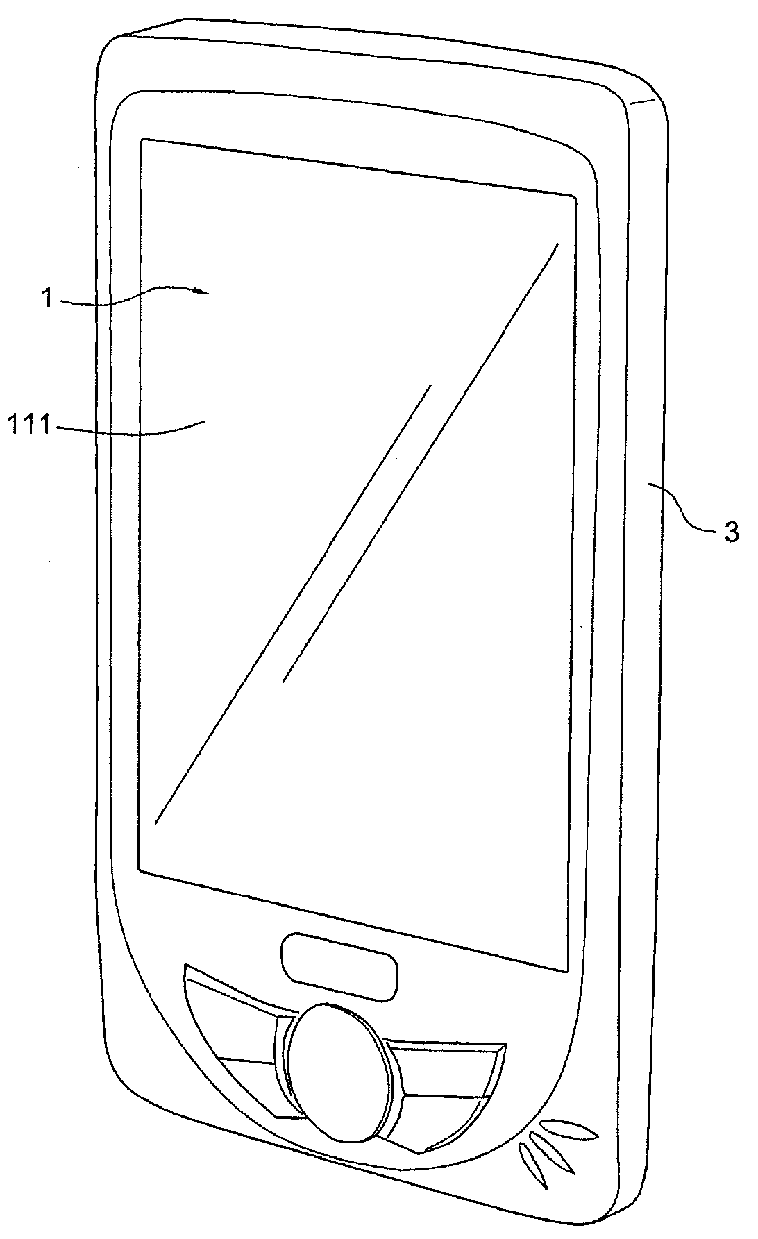
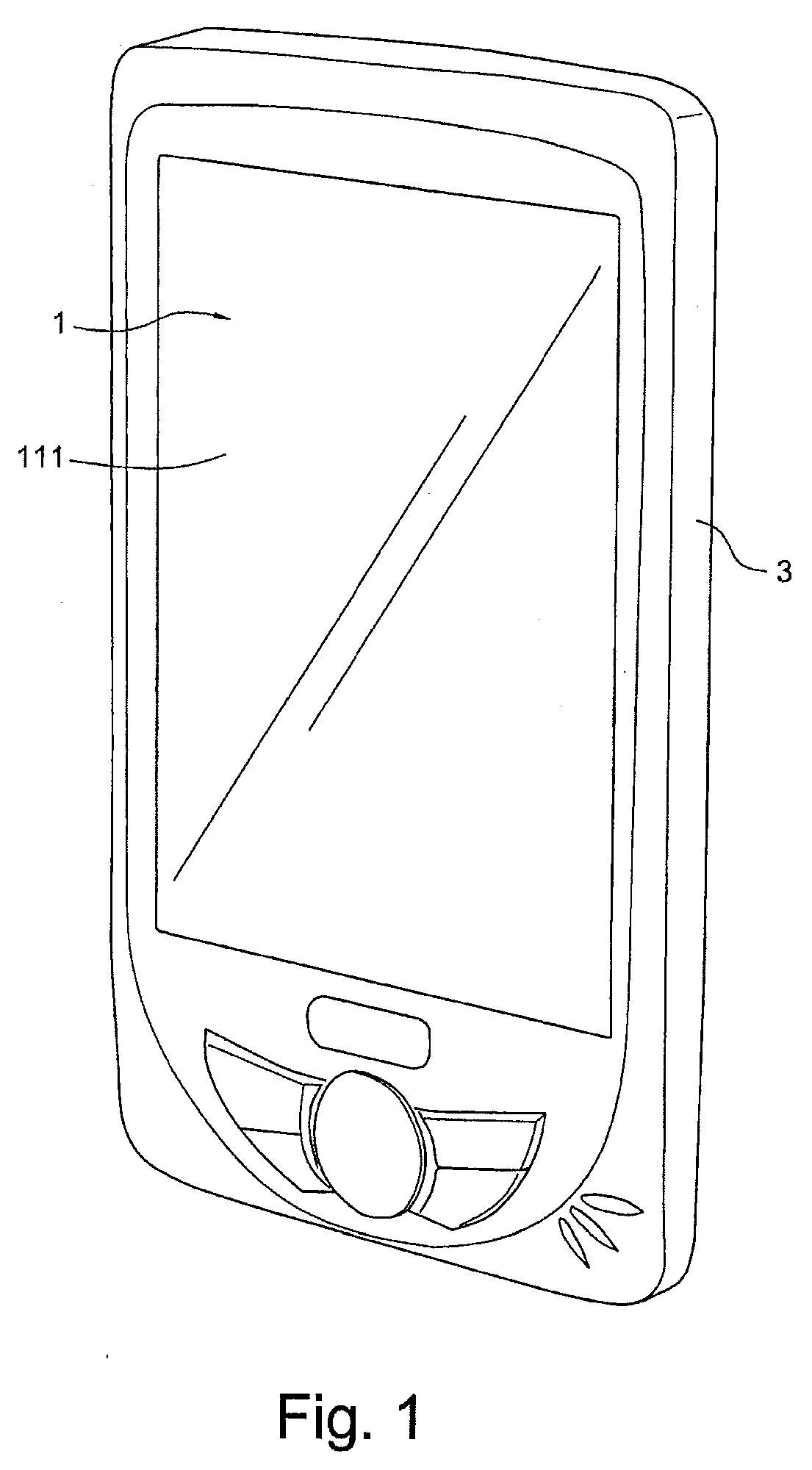
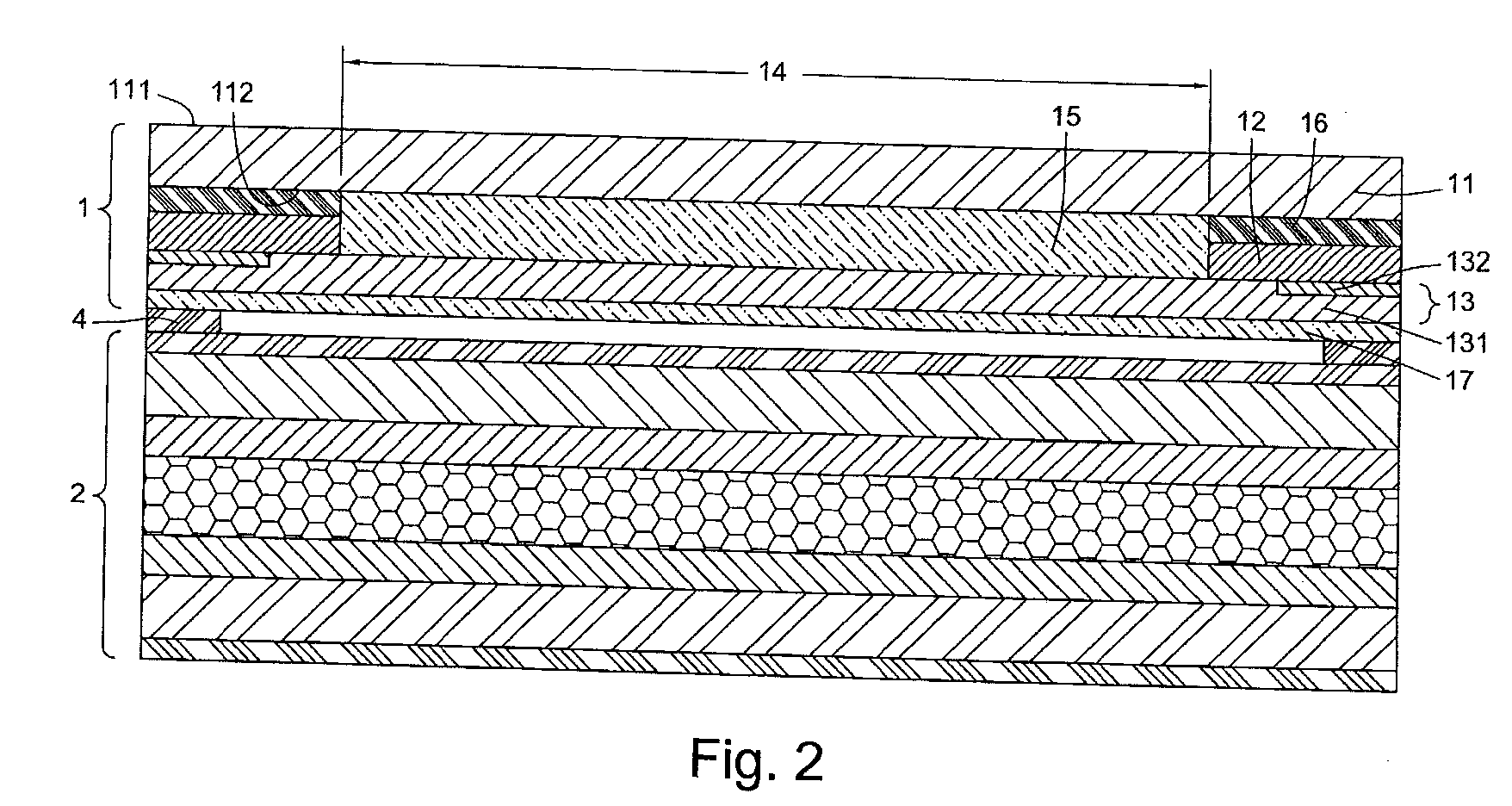
[0021]FIG. 1 is a perspective view showing an electronic device with an integrally-formed capacitive touch panel 1 of the invention. The capacitive touch panel 1 is assembled in a shell 3 of the electronic device, as illustrated in FIG. 1. FIG. 2 is a sectional view showing the capacitive touch panel 1 disposed on a display panel 2 according to one exemplary embodiment of the invention. In the present invention, the capacitive touch panel 1 includes a singular substrate 11, a mask layer 12 and a sensing circuit 13. The singular substrate 11, the mask layer 12 and the sensing circuit 13 are integrally formed. Therefore, there is no need to adopt other substrates for the integrally-formed capacitive touch panel 1, and there is no need to perform lamination in the assembly of the present touch panel as required in the conventional touch module. The details are illustrated as below.

[0022]The singular substrate 11 may be made of glass material to form a singular lens substrate. The singu...


PUM


Abstract

An integrally-formed capacitive touch panel is disclosed including: a singular lens substrate, a mask layer, and a sensing circuit integrally coupled with said singular lens substrate. Said singular lens substrate, said mask layer, and said sensing circuit are integrally formed.

Description

BACKGROUND[0001]1. Field of the Invention[0002]The invention relates to a touch panel, especially to a capacitive touch panel assembled with a display panel.[0003]2. Description of the Related Art[0004]Most electronic devices, such as PDA, palm-sized PC and information appliance, have a touch display panels. The touch display panel includes a lens, a display panel and a touch panel arranged between the lens and the display panel. In the prior art, the lens and the touch panel are separately formed on different substrates, which are usually glass substrates. The lens and the touch panel are then laminated to form a touch module. The touch module is further stacked up with and attached to the display panel to form the touch display panel. A user can touch objects displayed on the touch display panel with his or her finger or a touch pen to input information or perform an operation.[0005]Please refer to FIG. 6. FIG. 6 is a sectional view of a conventional touch display panel. As illust...

Claims


Application Information

Patent Timeline
Patent Type & Authority Applications(United States)
IPC IPC(8): G06F3/045
CPCG06F3/044G06F3/041G06F3/04164G06F3/0443G06F3/0445G02F1/13338G06F1/1643G06F3/0412G06F2203/04111G06F2203/04112
Inventor LIU, CHEN-YUHO, KWAN-SIN
Owner TRENDON TOUCH TECHNOLOGY CORPORATION
Learn More