
Dust collecting device for vacuum cleaner

a technology for collecting devices and vacuum cleaners, which is applied in the direction of auxillary pretreatment, cleaning filter means, separation processes, etc., can solve the problems of poor dust collection performance of the primary cyclone dust collection unit that collects a major portion of dust, difficult fabrication of related art dust collection devices, and complicated structure, so as to improve the performance of the dust collection device and improve the dust collection performan

Active Publication Date: 2009-08-20
LG ELECTRONICS INC
View PDF16 Cites 83 Cited by
  • Summary
  • Abstract
  • Description
  • Claims
  • Application Information

AI Technical Summary

Benefits of technology

The present invention provides a dust collecting device for a vacuum cleaner that has improved dust collecting performance. The device includes a primary cyclone unit with two parallel primary cyclones for separating dust from air, and a secondary cyclone unit at a downstream of the primary cyclones for cleaning the air again by the cyclone principle. The device also includes a suction guide portion for guiding the air containing dust to the primary cyclones. The dust collecting container has the primary cyclones and a primary dust storage portion for storing dust separated by the primary cyclones. The invention solves the problems of poor dust collecting performance and difficult fabrication, cleaning, and determining the amount of dust accumulated in the primary dust storage portion.

Problems solved by technology

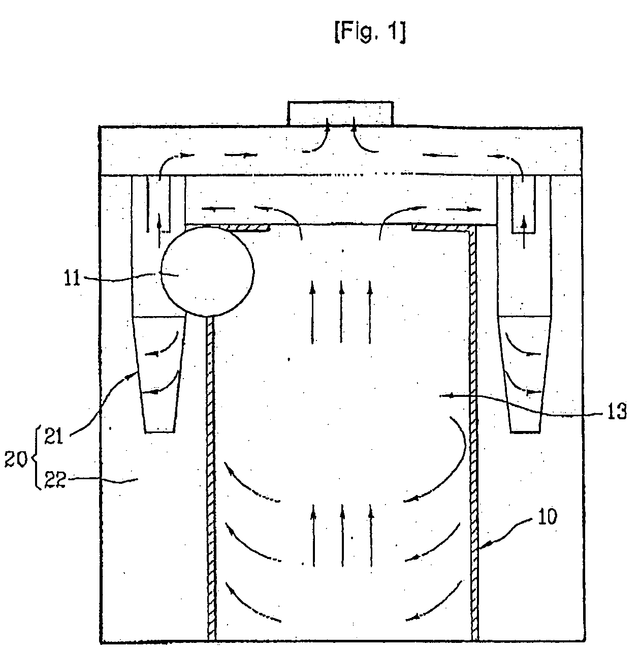
However, the related art dust collecting device has a problem in that a dust collecting performance of the primary cyclone dust collecting unit that collects a major portion of the dust is poor because the foreign matters, such as dust, is separated and collected only with single primary cyclone unit.
Moreover, the related art dust collecting device has problems in that fabrication of the related art dust collecting device is difficult, a structure is complicate, air tightness between the cleaner body and the suction pipe is poor, because the suction pipe is connected to an outside wall of the primary cyclone unit in a tangential direction substantially for guiding air containing dust in a substantially tangential direction of the inside wall of the primary cyclone unit.
Moreover, since an inside diameter of the primary cyclone unit is the same in overall, the dust in the dust storage portion at a lower portion of the primary cyclone unit flies to an upper portion of the primary cyclone unit by the spiral circulation of the air in the primary cyclone unit, thereby leading the dust collecting performance poor.
Furthermore, because the secondary cyclone unit is around the primary cyclone unit, and the secondary dust storage portion is around the primary dust storage portion, the related art dust collecting device has problems in that fabrication of the dust collecting device is difficult, cleaning of the secondary dust storage portion is difficult due to a small width of the secondary dust storage portion, and determining an amount of dust accumulated in the primary dust storage portion is difficult.

Method used


Image

  • Dust collecting device for vacuum cleaner
  • Dust collecting device for vacuum cleaner
  • Dust collecting device for vacuum cleaner

Examples


Embodiment Construction

[0050]Reference will now be made in detail to the preferred embodiments of the present invention, examples of which are illustrated in the accompanying drawings. Wherever possible, the same names and reference numbers will be used throughout the drawings to refer to the same or like parts, and repetitive description of which will be omitted.

[0051]As one embodiment of a vacuum cleaner having a dust collecting device in accordance with a preferred embodiment of the present invention applied thereto, a canister type vacuum cleaner will be described.

[0052]The vacuum cleaner includes a suction nozzle for drawing air containing foreign matters while moving along a floor to be cleaned, a cleaner body provided separate from the suction nozzle, and a connection pipe connected between the suction nozzle and the cleaner body for guiding contaminated air from the suction nozzle to the cleaner body.

[0053]The suction nozzle has a predetermined size of nozzle suction opening in a bottom for drawin...


PUM

PropertyMeasurementUnit
distanceaaaaaaaaaa
areaaaaaaaaaaa
sizesaaaaaaaaaa

Abstract

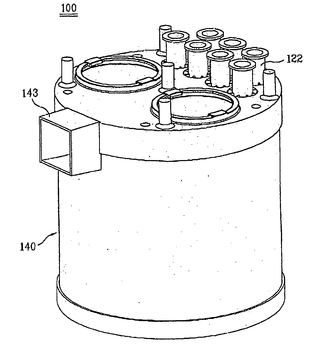
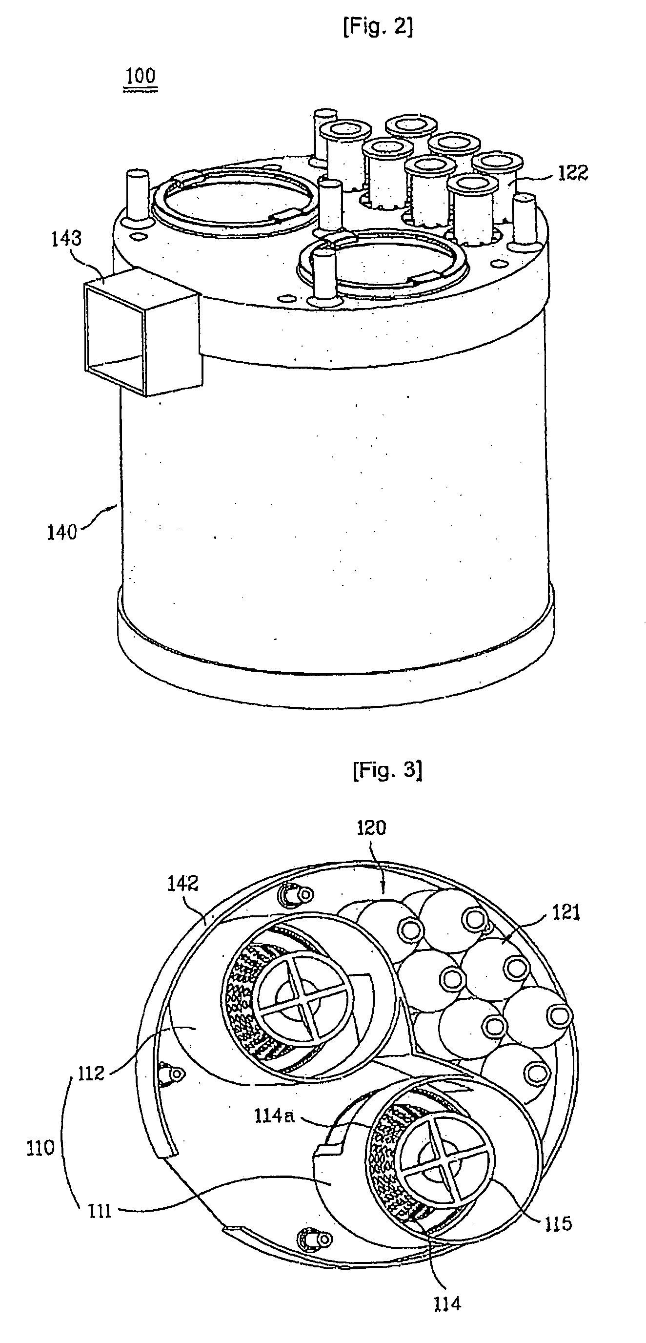
Object of the present invention is to provide a dust collecting device (100) for a vacuum cleaner of which dust collecting performance is improved. For this, the dust collecting device (100) includes a primary cyclone unit (110) having two parallel primary cyclones (111,112) for separating dust form air introduced therein by a cyclone principle, and a secondary cyclone (120) unit at a downstream of the primary cyclones (111,112) for cleaning the air again by the cyclone principle.

Description

TECHNICAL FIELD[0001]The present invention relates to a dust collecting device for a vacuum cleaner, and more particularly, to a dust collecting device for a vacuum cleaner which collects dust by a cyclone principle.BACKGROUND ART[0002]In general, the cyclone dust collecting device is applied to a vacuum cleaner, for separating foreign matters, such as dust, from circulating air, to collect the dust.[0003]The cyclone principle utilizes a difference of centrifugal forces for separating foreign matters, such as dust, from air circulating in a spiral.[0004]Recently, the cyclone dust collecting device, collecting dust by using the cyclone principle, is generally applied to the vacuum cleaner owing to advantages of the cyclone dust collecting device in that dust collecting performance is good and dust can be removed easily compared to a bag-type dust collecting device in which a dust bag is mounted in an air flow passage for collecting dust.[0005]A related art dust collecting device for ...

Claims


Application Information

Patent Timeline
Patent Type & Authority Applications(United States)
IPC IPC(8): A47L9/16
CPCA47L9/1616A47L9/1625A47L9/1658A47L9/165A47L9/1641Y10S55/03A47L9/16
Inventor HYUN, KIE TAKSON, YOUNG BOKJEONG, KYEONG SEONKIM, IL JOONG
Owner LG ELECTRONICS INC
Learn More